Concurrent Injection Of Liquid And Gaseous Fuels In An Engine

a fuel injection and gaseous fuel technology, applied in the direction of liquid fuel feeders, machines/engines, mechanical equipment, etc., can solve the problems of excessive exhaust emissions, undesirable liquid injection during the middle and end of the injection,

Inactive Publication Date: 2010-08-12
THE UNIV OF BRITISH COLUMBIA
View PDF9 Cites 66 Cited by
  • Summary
  • Abstract
  • Description
  • Claims
  • Application Information

AI Technical Summary

Benefits of technology

[0026]controlling the mass ratio of the liquid and gaseous fuels during the injecting step so that a majority of the liquid fuel is injected closer to the start rather than the end of the injecting step.

Problems solved by technology

Liquid injected during the middle and end of the injection is undesirable.
If the initial liquid / gas mass ratio is too high, then liquid atomization can be poor, leading to excessive exhaust emissions.

Method used


Image

  • Concurrent Injection Of Liquid And Gaseous Fuels In An Engine
  • Concurrent Injection Of Liquid And Gaseous Fuels In An Engine
  • Concurrent Injection Of Liquid And Gaseous Fuels In An Engine

Examples


first embodiment

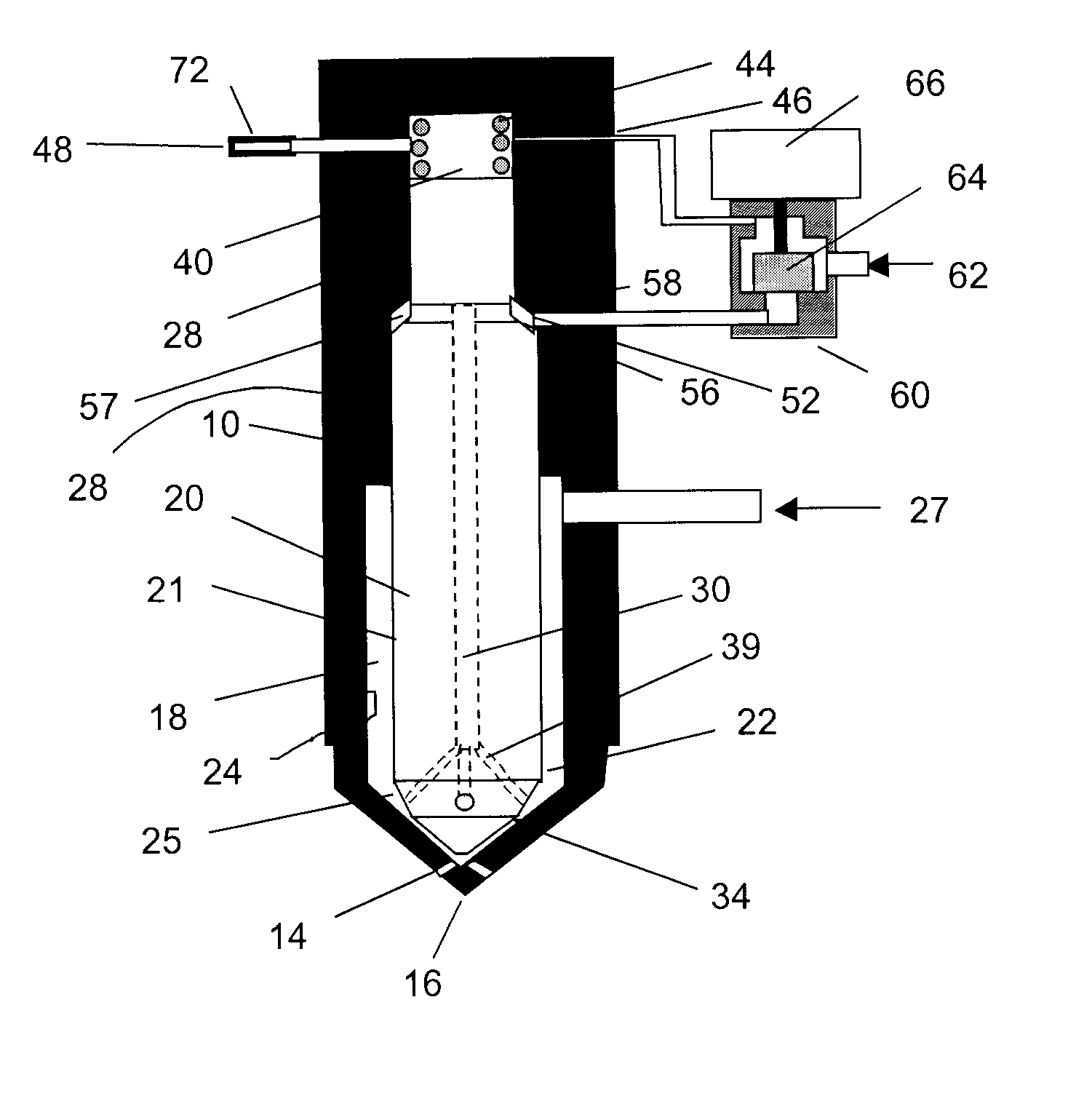
[0046]Referring to FIG. 1, a fuel injector according to a first embodiment of the invention is shown. The injector can be located in an aperture in a cylinder head of an internal combustion engine.

[0047]The fuel injector includes injector body 10 having injection holes or orifices 14 at a first end 16 thereof. Injector body 10 includes central cavity 18 formed by cavity wall 24 and includes slidable needle 20 therein. At a lower portion of central cavity 18, needle 20 forms lower chamber 22, which serves as a plenum or small accumulator, annularly disposed between needle 20 and cavity wall 24. The lower chamber includes tapered end 25 at first end 16 of the injector wherein injection holes 14 allow the combustion chamber of an internal combustion engine (not shown) to be in fluidic communication with tapered end 25 of the lower chamber when needle 20 is lifted from seat 34. The lower chamber further communicates with gas inlet port 27 operable to supply the lower chamber with a quan...

second embodiment

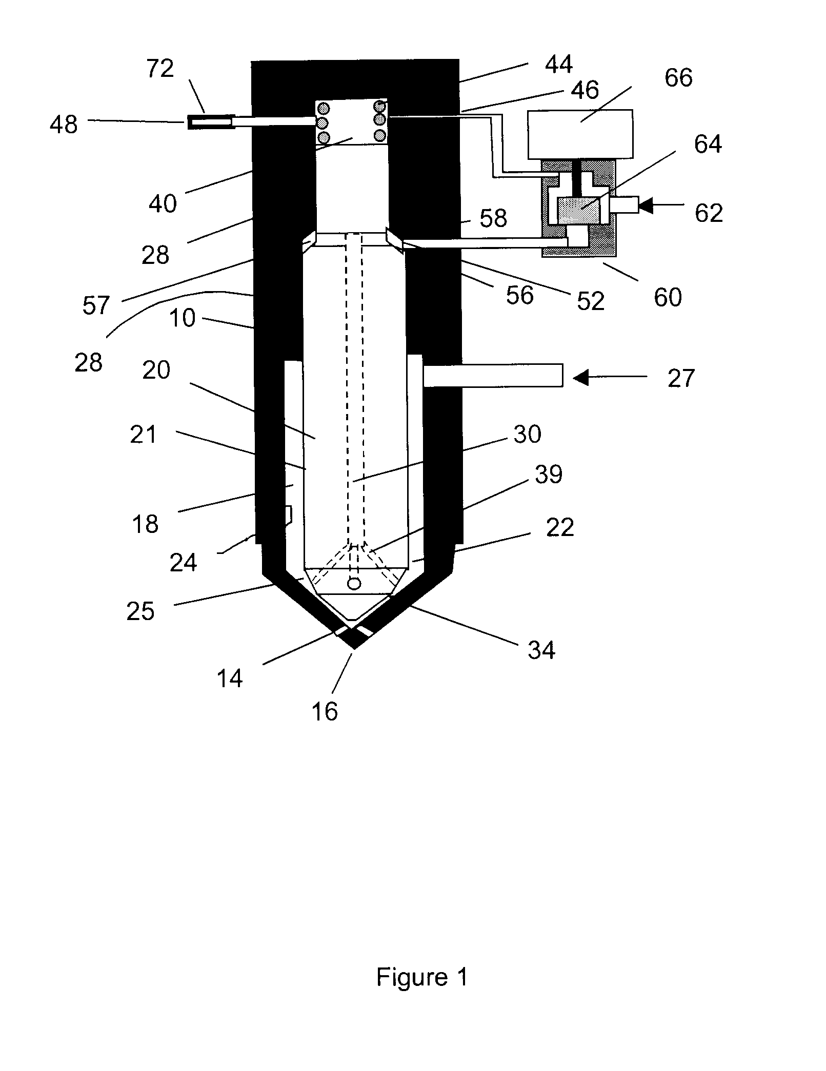
[0058]FIG. 2 shows a second embodiment of the fuel injector in which parts identical to those of the first embodiment are labeled with the same reference number. Like the first embodiment, the second embodiment shown in FIG. 2 middle chamber 57 is defined between needle shoulder 56 and contact seal 58. However, the second embodiment uses simple on-off control valve 70 rather than 3-way control valve 60, which is used by the first embodiment. In the second embodiment, the fuel injector is further provided with supply orifice 79 between liquid supply line 62 and control valve 70.

[0059]The operation of the fuel injector of FIG. 2 can be understood by considering pressures at 5 locations and fluid resistances at 3 locations,[0060]PD—pressure at drain outlet port 48 which in most instances is atmospheric pressure; (P˜0)[0061]PL—supply pressure of liquid supply line 62[0062]PG—gas rail pressure at gaseous fuel inlet port 27 which can be several hundred bar;[0063]Pup—pressure in upper cham...

third embodiment

[0075]Referring now to FIG. 3, a further embodiment of the present invention is shown. According to this embodiment, needle 20 includes enlarged central passage 140 extending to the upper end of the needle. Central passage 140 contains plunger 142, preferably with a substantially liquid-tight sliding seal. In this instance, persons skilled in the technology will understand that the word “substantially” means that plunger 142 and passage 140 are made with a matched fit or with a seal that reduces any leakage to an amount that does not affect the operation of the apparatus as described herein. Plunger 142 is always in contact with injector cap 144 although it is not fastened to the cap.

[0076]The contact between cap 144 and plunger 142 is due to the balance of forces. The injector includes upper chamber 146 which is supplied with liquid from supply line 62. Orifice 148, which is located between upper chamber 146 and supply line 62, throttles the liquid flow to upper chamber 146. The li...


PUM


Abstract

Disclosed is a method and corresponding fuel injector for injecting gaseous and liquid fuel into an engine. The method comprises delivering a liquid fuel to a fuel injector, delivering a pressurized gaseous fuel to the fuel injector, entraining the liquid fuel within the gaseous fuel within a chamber of the fuel injector and injecting the gaseous fuel and atomized liquid fuel into the combustion chamber. The liquid fuel can be passed through and dispensed from a needle into a chamber in the injector nozzle where it is entrained in the gaseous fuel during an injection event. The liquid/gas mass ratio is controlled by the needle movement, hydraulic resistances or electronic valves so that the majority of the liquid is injected during the first part of the gas injection. The injector can be used for late cycle direct injection of natural gas, or any number of gaseous fuel blends combined with many liquid fuels such as diesel, biodiesel and DME.

Description

BACKGROUND OF THE INVENTION[0001]1. Field of Invention[0002]The present invention relates to fuel injection in general and in particular to a method and apparatus for the injection of liquid and gaseous fuels directly into the combustion chamber of an engine.[0003]2. Description of Related Art[0004]The book, The Modern Diesel Engine, (Geoffrey Smith, Ed., Ilife and Sons Ltd, London, 1942) describes the most advanced practical and experimental diesel engine technology up to about 1942. The Ricardo Comet, Lanova air-cell and Acro air-cell systems use a small side chamber connected to the main combustion chamber by a small passage. When the piston moves down, the high pressure gases stored in the side chamber rush through the passage to the main chamber, creating a high-velocity jet that may be used for atomization and mixing of the jet. Cummins Engine Co. produced engines in the 1930's with an air-cell in the piston, which produced an air jet aimed directly at the fuel injector, suppo...

Claims


Application Information

Patent Timeline
Patent Type & Authority Applications(United States)
IPC IPC(8): F02M43/00F02D19/06F02M21/02F02M63/00
CPCF02D19/0647F02D19/081F02M37/0064F02M43/04F02M61/042F02D19/0694Y02T10/36F02D19/061F02D19/0652F02D19/0689F02M61/045Y02T10/30
Inventor ROGAK, STEVEN N.BUSHE, WILLIAM KENDALMCTAGGART-COWAN, GORDON
Owner THE UNIV OF BRITISH COLUMBIA
Why Eureka
Try Eureka