Methods for controlling temperatures in the environments of gas and oil wells

a technology for oil wells and environments, applied in the direction of fluid removal, borehole/well accessories, insulation, etc., can solve the problems of limiting the transfer of heat subsequently, further melting, etc., and achieves the effects of reducing the melting of glaciers, reducing the melting point, and reducing the thermal conductivity

Inactive Publication Date: 2010-08-12
COLGATE SAM O +1
View PDF99 Cites 20 Cited by
  • Summary
  • Abstract
  • Description
  • Claims
  • Application Information

AI Technical Summary

Benefits of technology

[0030]Methods and equipment are provided (1) for controlling temperatures in the environments of oil, gas condensate, or gas wells and (2) for reducing the melting of glaciers and ice dams through the deployment of hydrate-forming substances. The environmental temperature control includes both (1a) active and (1b) passive methods or a combination of the two. The active method involves employing a vapor-compression refrigerator/heat pump cycle in an annulus lying between the relatively hot production string and the relatively cold outer pipe. In this method, heat is pumped away from the relatively cold outer pipe so that the ΔT becomes small there; and heat is pumped toward the relatively hot production string so that the ΔT becomes small there as well.
[0031]The passive methods include: deploying cold hydrate-forming fluids into the external ice-laden environment of an oil, gas condensate, or gas well in a permafrost area and allowing those hydrate forming fluids to mix with any melt-water that may be present or that may subsequently form due to the loss of heat from the oil, gas condensate, or gas well. The mixture of the h

Problems solved by technology

Additionally, the thermal conductance of melt-water is higher than those of ice or hydrate; consequently, the elimination of melt-water limits the transfer of heat subsequently.
Of

Method used


Image

  • Methods for controlling temperatures in the environments of gas and oil wells
  • Methods for controlling temperatures in the environments of gas and oil wells
  • Methods for controlling temperatures in the environments of gas and oil wells

Examples


Embodiment Construction

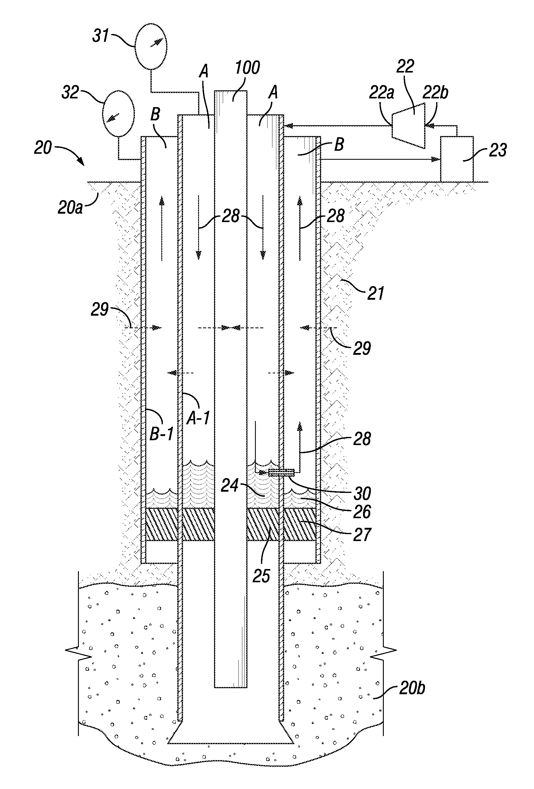
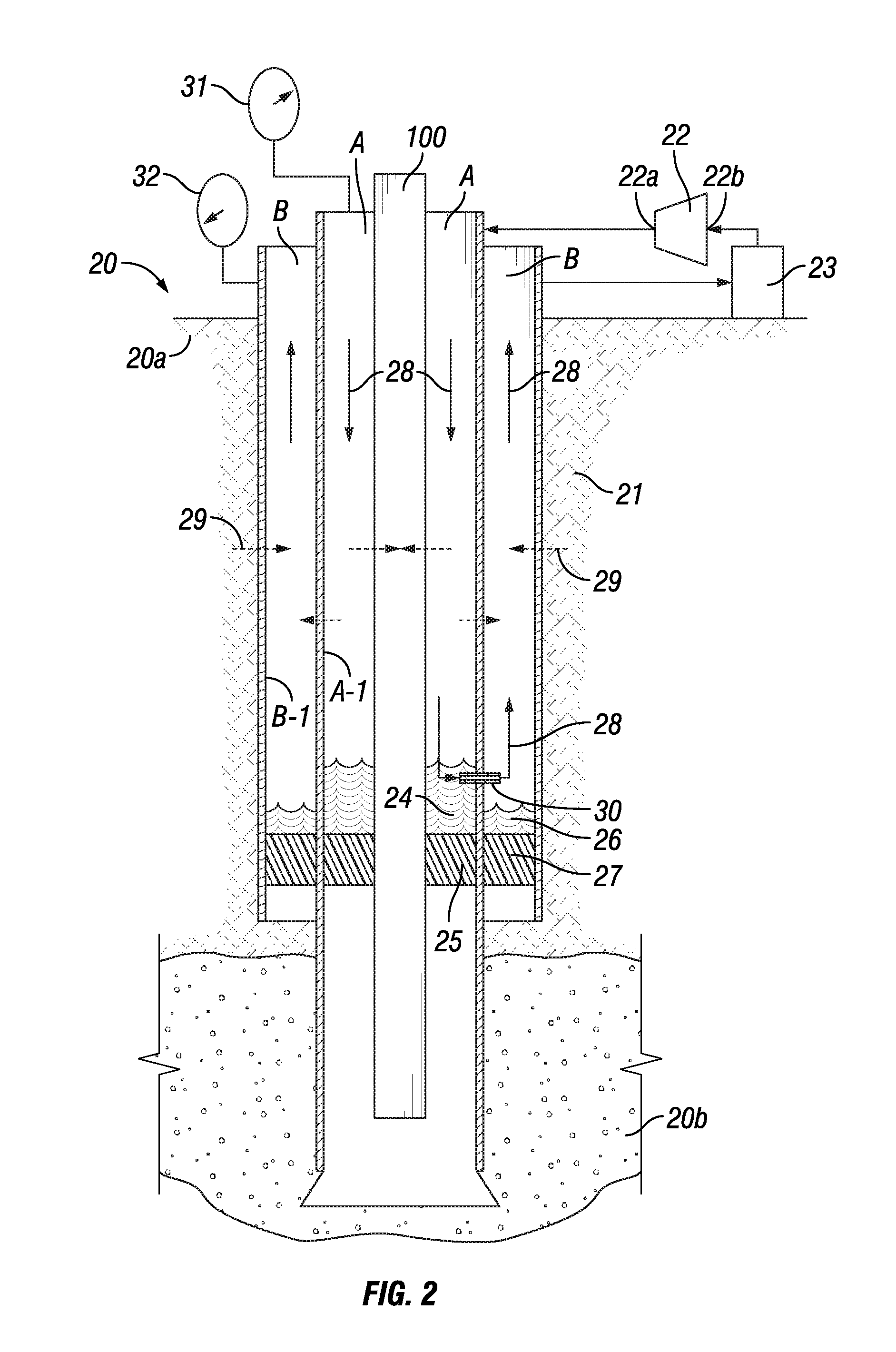
[0058]In one aspect, the present invention relates to ice-laden environments such as those in permafrost areas where a proactive approach is taught herein (1) limiting the consequences of the transfer of heat from the relatively hot produced fluids into the ice in the environment surrounding the production string, impeding the melting of ice, and thereby (2) limiting the transfer of heat. In this aspect, the present invention teaches the deployment of cold hydrate-forming fluids into the external ice-laden environment near the production string. If subsequently the transfer of heat leads to the melting of some of this ice, the previously deployed cold hydrate-forming fluids will convert the melt-water into hydrate form. The melting point of the hydrates will typically be much higher than that of ice, so subsequent melting will be diminished or eliminated. Additionally, the thermal conductance of melt-water is higher than those of ice or hydrate; consequently, the elimination of melt...


PUM


Abstract

Methods and apparatus are provided for controlling temperatures in the environments of oil, gas condensate, or gas wells. Methods are provided for reducing the melting of glaciers and ice dams through the deployment of hydrate-forming substances. Active methods involve employing a vapor-compression refrigerator/heat pump cycle in an annulus lying between the relatively hot production string and the relatively cold outer pipe. Passive methods include: deploying cold hydrate-forming fluids into the external ice-laden environment of an oil, gas condensate, or gas well in a permafrost area and allowing those hydrate forming fluids to mix with any melt-water that may be present or that may subsequently form due to the loss of heat from the oil, gas condensate, or gas well. Mixtures of the hydrate forming fluids and the melt-water will set up into a solid having a much higher melting point and a much lower thermal conductivity than those of ice.

Description

CROSS-REFERENCE TO RELATED APPLICATIONS[0001]This application claims the benefit of the filing date of and priority to U.S. Provisional Application Ser. No. 61 / 207,464 entitled “Methods for controlling temperatures in the environments of gas and oil wells” and filed Feb. 12, 2009, Confirmation No. 3995. Said provisional application is incorporated by reference herein.STATEMENT REGARDING FEDERALLY SPONSORED RESEARCH OR DEVELOPMENT[0002]Not Applicable.BACKGROUND OF THE INVENTION[0003]1. Field of the Invention[0004]Embodiments disclosed herein relate generally to the recovery of oil, gas condensate, and gaseous hydrocarbons. In particular, embodiments disclosed herein relate to the recovery of oil, gas condensate, and gaseous hydrocarbons from subterranean petroliferous reservoirs wherein there is a need to limit the transfer of heat from the relatively hot produced fluids into the environment surrounding the production string of pipe.[0005]2. Background Art[0006]Production of oil, gas...

Claims


Application Information

Patent Timeline
IPC IPC(8): E21B43/24
CPCE21B36/003
Inventor COLGATE, SAM O.HORTON, ROBERT L.
Owner COLGATE SAM O
Why Eureka
Try Eureka