
Hermetic electrical ports in liquid crystal polymer packages

Active Publication Date: 2010-08-12
LINDEN PHOTONICS
View PDF20 Cites 13 Cited by
  • Summary
  • Abstract
  • Description
  • Claims
  • Application Information

AI Technical Summary

Benefits of technology

[0018]In one aspect, the complementary configured mating sections are both made of LCP, and in another, the compl

Problems solved by technology

However, if the package has electrical leads that enter or exit the package for purposes of connecting with exterior components, these electronic ports become points for moisture entry and hermeticity is compromised.
Thermoplastics had not had the moisture barrier properties to achieve hermeticity.
Hermetic electrical ports in LCP packages have long presented a technical challenge.
Although molded LCP has excellent moisture barrier properties, design of an electrical port such that metal leads can enter and exit without compromising hermeticity is challenging primarily because adhesion between LCP and metal is not good.
LCPs are chemically inert, which is desirable in many applications, but is an impediment in achieving good adhesion to other materials.
The permeability of LCPs to oxygen is also extremely low.

Method used


Image

  • Hermetic electrical ports in liquid crystal polymer packages
  • Hermetic electrical ports in liquid crystal polymer packages
  • Hermetic electrical ports in liquid crystal polymer packages

Examples


example 1

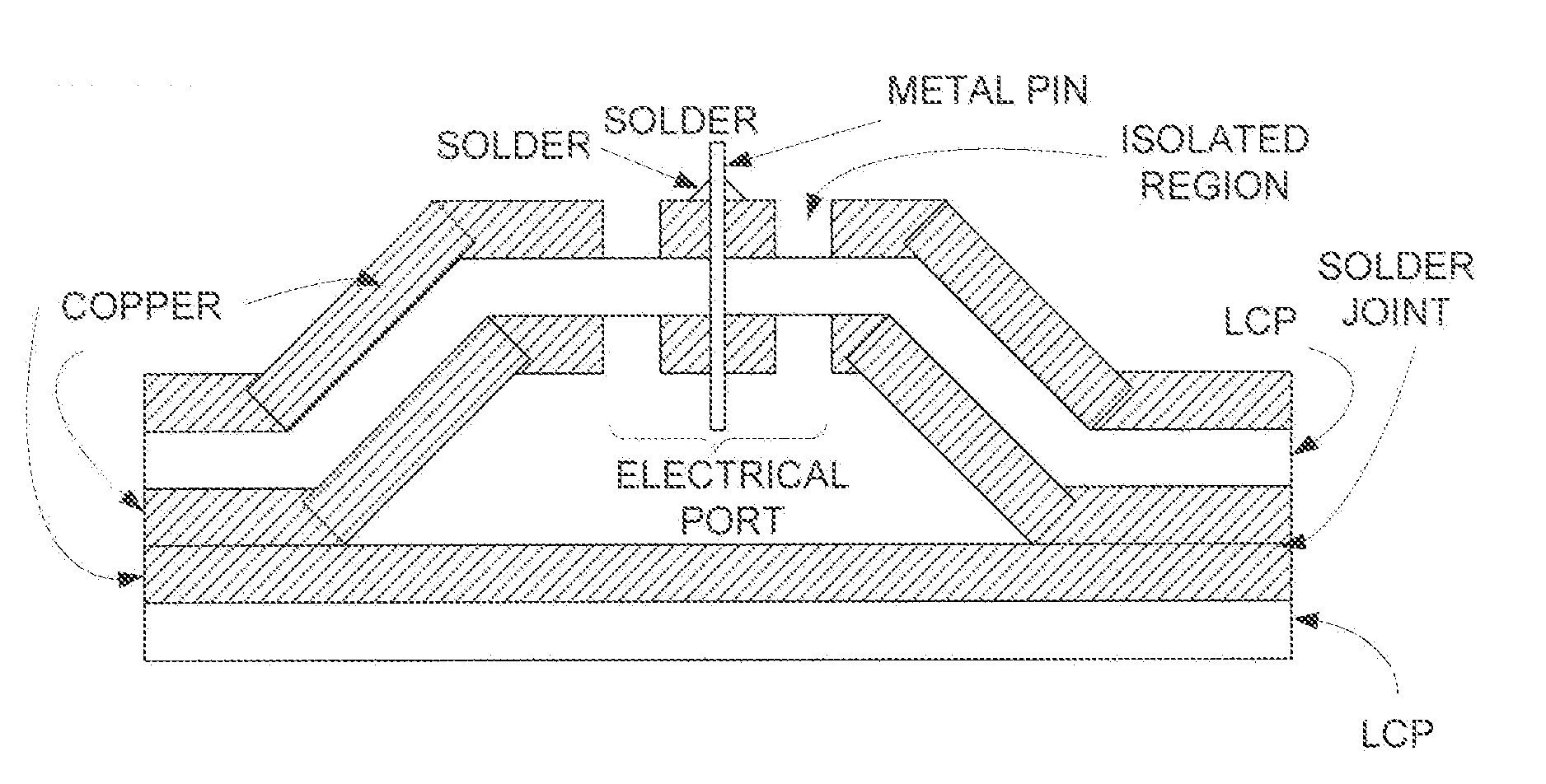
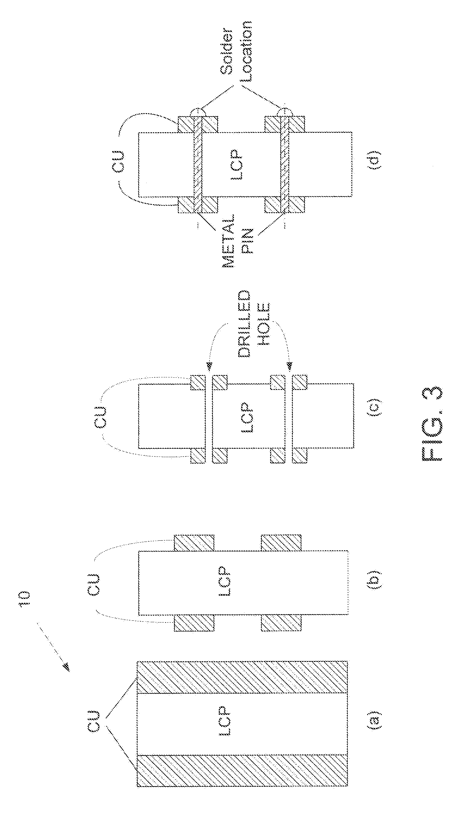
[0064]In this example, Ticona Vectra A950 LCP resin was molded into suitable base and lid structures, including energy directors for ultrasonic welding. The perimeter of the base and lid was approximately 1″ square and height of the combined base and lid was approximately 0.5″. Several bases were filled with two-component ACE brand epoxy and the epoxy was allowed. to set. Subsequently, the epoxy filled bases and LCP lids were ultrasonically bonded using standard techniques as shown in the photograph of FIG. 15. Small sections of ULTRALAM3850 double copper clad LCP, acquired from Rogers Corporation, was cut into 1″ squares, the copper was etched from one side, and the LCP side was thermally bonded to the LCP lid. A copper pin was inserted into the package through a small hole drilled in the copper pads and the pin was soldered to the copper pad.

[0065]In FIG. 15, the sample marked EO has an epoxy filled base, but the lid is not ultrasonically bonded to the base, but instead sits on it...

example 2

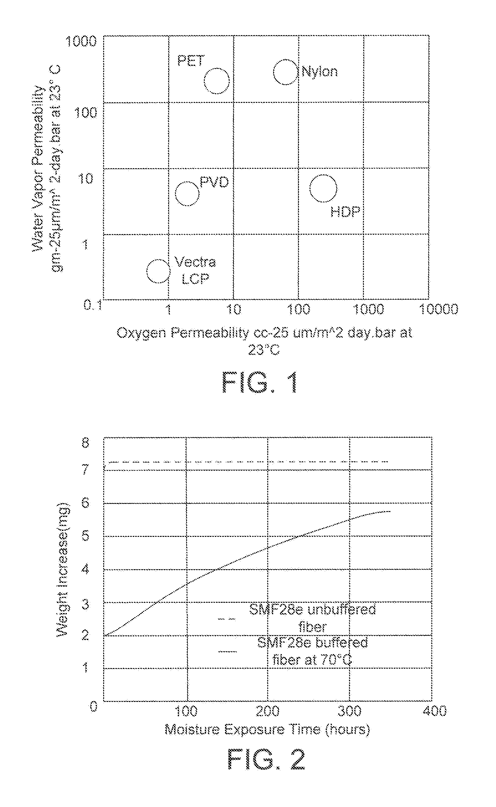
[0067]In this example, ULTRALAM3850 pieces, approximately 3″ square, were cut out of larger sheets. A disk shaped puck of epoxy was placed between two of the cut out pieces. One of the ULTRALAM pieces had one electrical port incorporated in it based on the design shown in FIG. 12. The two pieces of ULTRALAM were then soldered along the perimeter using Sn60 / Pb40 solder so that the epoxy puck was completely surrounded with ULTRALAM3850. All samples were placed in a 900 C oven in a 100% relative humidity environment. The samples were removed periodically and weighed. In addition, one puck of epoxy was placed in the test chamber unpackaged in ULTRALAM so that it was directly exposed to the humid environment. This test would determine if the weight of the unprotected epoxy puck would increase much faster than the other samples.

[0068]FIG. 17 shows the results over 2550 hours. The weight of the unprotected epoxy puck increases fast and then starts to decrease. This decrease is because the ...


PUM

PropertyMeasurementUnit
Diameteraaaaaaaaaa
Shapeaaaaaaaaaa
Areaaaaaaaaaaa

Abstract

A packaging system having a housing for providing a hermetically sealed interior space for receiving and supporting optoelectronic components. The housing has at least one section of wall comprising a layer of liquid crystal polymer (LCP). At least one hermetically sealed electrical port is formed in the LCP wall section over a predetermined area and comprises a layer of metal adhered to and overlying the predetermined area on the of the LCP wall section. An electrode passes through the metal from the exterior of the system to the interior space to provide an electrical communication path between the optoelectronic components and the exterior of said packaging system. A solder joint is formed between the electrode and the layer of metal to provide a hermetic connection between the layer of metal and the electrode to assure that the hermeticity of the housing remains unchanged with the electrical port present.

Description

CROSS REFERENCE TO RELATED APPLICATION[0001]This application claims the benefit of priority from U.S. Provisional Patent Application No. 61 / 150,744 filed on Feb. 7, 2009 in the name of Amaresh Mahapatra, et al. with the title HERMETIC ELECTRICAL PORTS IN LIQUID CRYSTAL PACKAGES, the entire contents of which are incorporated herein by reference.FIELD OF THE INVENTION[0002]This invention relates to a method of fabricating hermetic electrical ports in molded LCP packages for electronic components and circuits.BACKGROUND OF THE INVENTION[0003]Because liquid crystal polymers (LCPs) have excellent moisture barrier properties, electronic components that are completely encased in a molded LCP package are hermetically insulated from exposure to atmospheric moisture. However, if the package has electrical leads that enter or exit the package for purposes of connecting with exterior components, these electronic ports become points for moisture entry and hermeticity is compromised.[0004]Air cav...

Claims


Application Information

Patent Timeline
IPC IPC(8): H05K5/06H05K5/03H01B5/00B23K37/00
CPCB23K1/0016H01L23/06H01L23/10H01L2924/09701H01L2924/0002H01L2924/00
Inventor MAHAPATRA, AMARESHO'RIORDEN, STEPHEN M.
Owner LINDEN PHOTONICS
Features
  • Generate Ideas
  • Intellectual Property
  • Life Sciences
  • Materials
  • Tech Scout
  • Unparalleled Data Quality
  • Higher Quality Content
  • 60% Fewer Hallucinations
Learn More