System and method for capturing and detecting symbology features and parameters

a symbology and feature technology, applied in the field of symbology readers, can solve the problems of difficult to provide such a trigger, increase the difficulty of barcode movement in a fashion, and inability to generate reliable triggers, etc., and achieve the effect of optimizing the efficiency of lap in neighborhood operations

Active Publication Date: 2010-08-12
COGNEX CORP
View PDF43 Cites 75 Cited by
  • Summary
  • Abstract
  • Description
  • Claims
  • Application Information

AI Technical Summary

Benefits of technology

[0013]This invention overcomes the disadvantages of the prior art by providing a system and method for capturing, detecting and extracting features of a symbology or ID, such as a 1D barcode, that employs an efficient processing system based upon a vision system on a chip (VSoC) architecture. Under the control of a CPU (also termed a “general purpose processor” herein), the VSoC illustratively provides a linear array processor (LAP) that is constructed with a single instruction multiple data (SIMD) architecture in which each pixel of the rows of the pixel array are directed to individual processors in a similarly wide array that defines the LAP. The pixel data are processed according to a front end (FE) process that performs rough finding and tracking of regions of interest (ROIs) that potentia

Problems solved by technology

For many applications, it may be difficult to provide such a trigger because (a) it may not be known by an outside source (i.e. the potential trigger generator) when the barcode is in the field of view (b) it may be impossible to generate a reliable trigger given the mechanics of the operation.
The difficulty increases when the barcode moves in a fashion that is not completely controlled in motion, position, and/or direction relative to the imaging system.
More, generally, the number of image-capture and image-decoding events per second inherent to the system limits the ability to adequately scan an ID.
Thus, rapid movement of the scanning appliance, and/or orienting the appliance at a steep angle with respect to the ID, can render most or all of the limited number of capture events inadequate to detect or decode the ID.
Moreover, it is recognized that certain aspects of the code itself can make it difficult to detect or decode it within a limited number of capture events—and a moving scanner typically results in a more limited group of usable image-captures.
In such cases, the initial capture settings may be inadequate and there may be latency until the final, more-sufficient capture settings are adjusted.
The number of captures available after this initial capture and adjustment latency may be quite small and make the detection and/or decoding of an ID difficult.
However, laser scanners employ mechanical parts, such as moving m

Method used


Image

  • System and method for capturing and detecting symbology features and parameters
  • System and method for capturing and detecting symbology features and parameters
  • System and method for capturing and detecting symbology features and parameters

Examples


Embodiment Construction

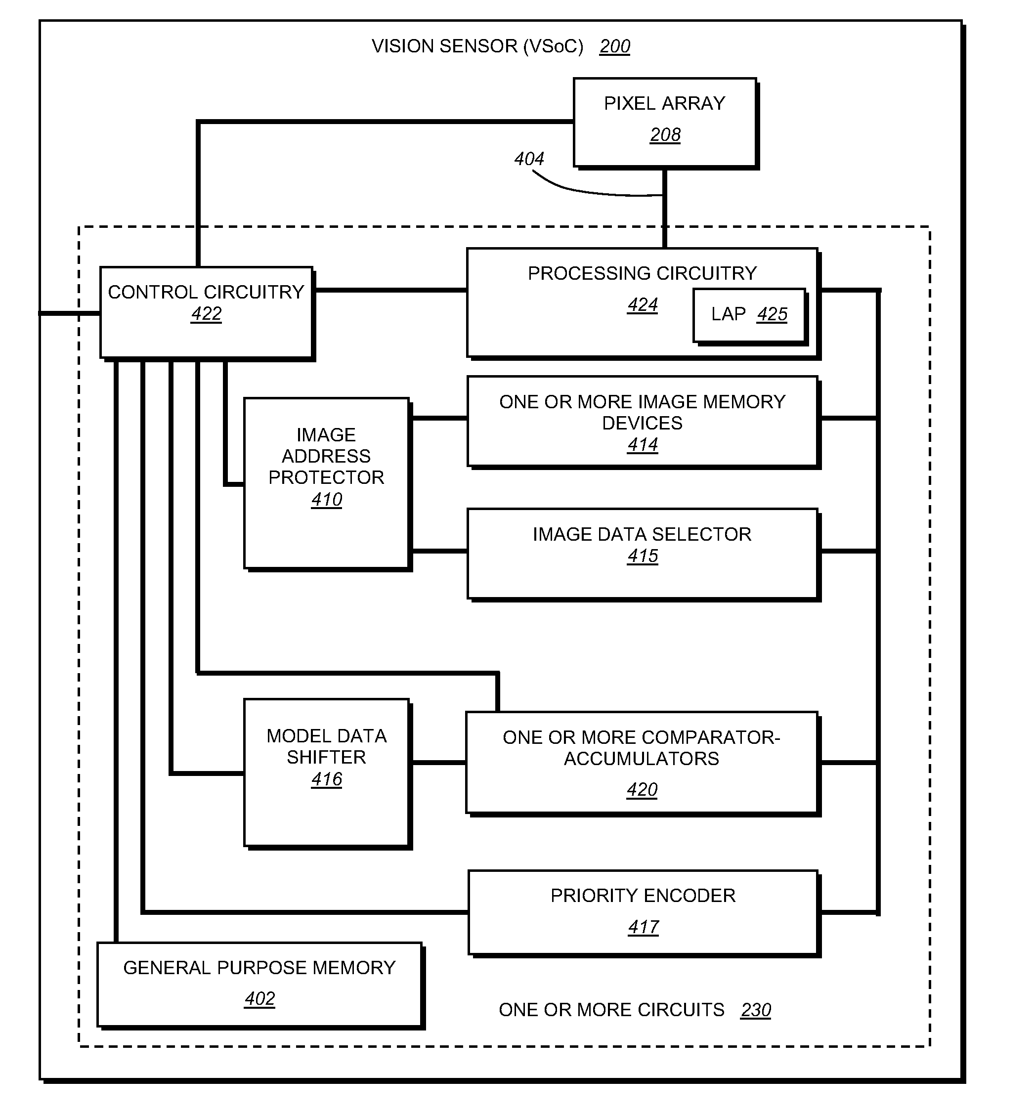
[0039]The system and method for capturing, detecting, identifying and extracting ID / barcode features according to illustrative embodiments is adapted to operate with a processor that defines an architecture capable of processing an entire row of data read-out from an interconnected pixel array in a discrete processing cycle (i.e. all data in a row being simultaneously processed with each clock cycle). To accomplish this, the overall VSoC processor is organized to include a wide on-bit data bus (for example a 1024×1 bus) between an image data storage memory (also having a storage array that is 1024 wide) and the pixel array (in this example, a 1024×768 pixel array with 8-bit or 6-bit pixels). This memory is interconnected by another similarly wide (1024×1, for example) bus to the image processing component, which is organized to process the entire row simultaneously using, for example, single-instruction, multiple-data (SIMD) processors that are very efficient at neighborhood operati...


PUM


Abstract

This invention provides a system and method for capturing, detecting and extracting features of an ID, such as a 1D barcode, that employs an efficient processing system based upon a CPU-controlled vision system on a chip (VSoC) architecture, which illustratively provides a linear array processor (LAP) constructed with a single instruction multiple data (SIMD) architecture in which each pixel of the rows of the pixel array are directed to individual processors in a similarly wide array. The pixel data are processed in a front end (FE) process that performs rough finding and tracking of regions of interest (ROIs) that potentially contain ID-like features. The ROI-finding process occurs in two parts so as to optimize the efficiency of the LAP in neighborhood operations—a row-processing step that occurs during image pixel readout from the pixel array and an image-processing step that occurs typically after readout occurs. The relative motion of the ID-containing ROI with respect to the pixel array is tracked and predicted. An optional back end (BE) process employs the predicted ROI to perform feature-extraction after image capture. The feature extraction derives candidate ID features that are verified by a verification step that confirms the ID, creates a refined ROI, angle of orientation and feature set. These are transmitted to a decoding processor or other device.

Description

[0001]This application claims the benefit of U.S. Provisional Application Ser. No. 61 / 151,715, filed Feb. 11, 2009, entitled SYSTEM AND METHOD FOR CAPTURING AND DETECTING SYMBOLOGY FEATURES AND PARAMETERS, the entire disclosure of which is herein incorporated by reference.FIELD OF THE INVENTION[0002]This invention relates to symbology readers, and more particularly to systems for capturing and identifying symbology, such as one-dimensional (1D) barcodes.BACKGROUND OF THE INVENTION[0003]Machine vision systems use image acquisition devices that include camera sensors to deliver information related to a viewed subject. The system then interprets this information according to a variety of algorithms to perform a programmed decision-making and / or identification function.[0004]Generally, symbology (also termed “ID”) reading entails the aiming of an image acquisition sensor (CMOS camera, CCD, etc.) at a location on an object that contains a symbol (a “barcode”), and acquiring an image of t...

Claims


Application Information

Patent Timeline
IPC IPC(8): G06K7/10
CPCG06K7/14
Inventor MOED, MICHAEL C.AKOPYAN, MIKHAIL
Owner COGNEX CORP
Why Eureka
Try Eureka