Device for optical characterization

a technology of optical characterization and sample, applied in the field of optical characterization samples, can solve the problems of inability to find and use the sensors for measuring properties which change over the spatial extension of the sample, and the failure of the spot sensors used for adsorption reflection measurement in particular, so as to achieve the effect of increasing the quality of measurement and achieving higher spectral separation

Active Publication Date: 2010-08-12
FULL PROCESS
View PDF9 Cites 7 Cited by
  • Summary
  • Abstract
  • Description
  • Claims
  • Application Information

AI Technical Summary

Benefits of technology

[0019]In a further example embodiment, a device for recording infrared radiation is situated in such a way that infrared radiation originating from the sample is recorded. The heat distribution in the sample may be measured by recording the infrared radiation. Thus, for example, the reaction progress may be tracked in reactions or the mixing progress may be tracked in mixtures. The device for recording the infrared radiation is an infrared-sensitive camera, for example. If an infrared-sensitive camera is used, for example, the difference in the heat capacity or the heat conductivity may also be measured using active thermography. For this purpose, first an image of the sample is recorded using the infrared-sensitive camera. After the image has been recorded, an infrared flash is emitted and an image is again recorded using the infrared-sensitive camera. A difference in the heat absorption by the sample may be recognized by comparing the two images which have been recorded using the infrared-sensitive camera. If further images are subsequently recorded using the infrared-sensitive camera, it may also be seen how rapidly the heat delivered by the infrared flash penetrates into the sample, i.e., the sample cools down again. A further advantage of active thermography is also that a mixing procedure may be observed and evaluated therewith.
[0020]To detect whether small quantities of sediment or particles are contained in the sample, it is preferable for the sample to be accommodated rotatably, to be able to swirl up the particles. In addition, multiple independent recordings are possible due to the rotation of the sample, whereby the quality of the measurement may be increased.
[0021]In a further example embodiment, at least one tunable filter is provided, to allow a decomposition of the recording into individual spectra. The at least one tunable filter element is preferably situated between the sample and the camera. By placing the filter element between the sample and the camera it is sufficient to only provide one single filter element. A separate filter element does not have to be provided on each light source. The recording may be decomposed into narrow-band spectra by using the at least one tunable filter element. A higher spectral separation is achieved by decomposition into spectra than when using a standard RGB color camera. In this way, phase boundaries may also be registered better, if the different substances only have a slight color difference.

Problems solved by technology

The spot sensors used for the adsorption and reflection measurement fail in particular, however, if the properties change spatially inside the liquid.
Sensors for measuring properties which change over the spatial extension of the sample are often also not available.

Method used


Image

  • Device for optical characterization
  • Device for optical characterization

Examples


Embodiment Construction

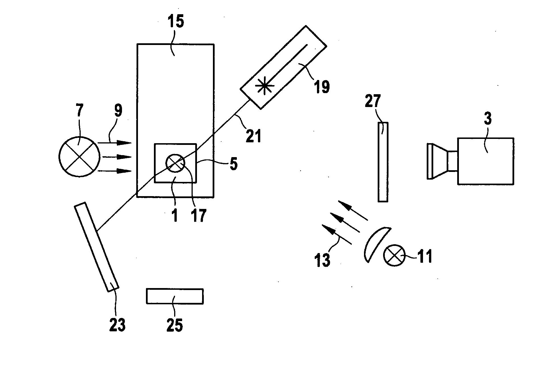
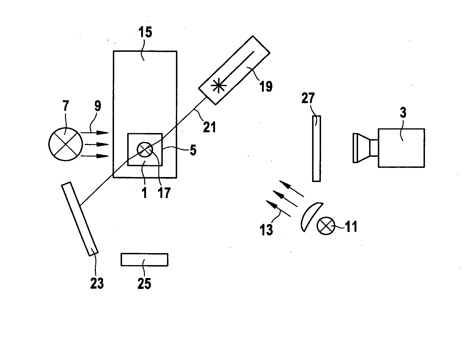
[0024]A schematic top view of a device implemented according to the present invention for the optical characterization of samples is shown in the single FIGURE.

[0025]A sample 1 is recorded by a camera 3 for the optical characterization. Sample 1 is generally a liquid which is accommodated in a receptacle container 5. Receptacle container 5 may be a cuvette, for example. To be able to optically characterize sample 1, it is necessary for receptacle container 5 to be transparent to radiation in the required wavelengths. The receptacle container may be manufactured from an amorphous plastic, such as PMMA, or also from glass or quartz glass, for example.

[0026]A first light source 7 is situated in such a way that sample 1 is transilluminated opposite to the viewing direction of camera 3. The emitted light of first light source 7 is shown by arrows 9. Sample 1 is transilluminated by first light source 7. For example, the spatial distribution inside the sample may be determined in the trans...


PUM


Abstract

A device for optical characterization of a sample is provided, the sample being accommodated in a receptacle container transparent to light. The device includes a camera, using which the sample may be detected, and a first light source is situated in such a way that the sample is transilluminated opposite to the viewing direction of the camera, a second light source is situated on the same side as the camera, and a laser source is situated transversely to the viewing direction of the camera.

Description

BACKGROUND OF THE INVENTION[0001]1. Field of the Invention[0002]The present invention relates to a device for optical characterization of samples.[0003]2. Description of Related Art[0004]Samples in the meaning of the present invention are any substances whose properties may be optically ascertained. In particular, samples in the meaning of the present invention are liquids. Properties which are to be studied are, for example, adsorption, reflection, phase formation, and further visible features, such as foaming, etc.[0005]Adsorption and reflection are generally determined by spot-measuring methods. In such a method, the sample is scanned vertically downward using a sensor having two photodiodes. Such a sensor is, for example, the sensor TURBISCAN™ from Quantachrome GmbH & Co. KG.[0006]The spot sensors used for the adsorption and reflection measurement fail in particular, however, if the properties change spatially inside the liquid. This is the case, for example, for the characteris...

Claims


Application Information

Patent Timeline
Patent Type & Authority Applications(United States)
IPC IPC(8): H04N7/18
CPCG01N21/272G01N21/4738G01N2021/6491G01N21/59G01N21/64G01N21/51
Inventor BRINZ, THOMASSEIFFERT, THOMAS
Owner FULL PROCESS
Why Eureka
Try Eureka