Electronic device and frequency converter of motor

a technology of electronic devices and frequency converters, which is applied in the direction of electrical equipment, electrical equipment contruction details, lighting and heating apparatus, etc., can solve the problems of affecting the size reduction of the frequency converter, each element of the circuit board has a potential risk of short-circuit or damage, and the air blown into the circuit board and contaminating internal devices, etc., to achieve the effect of removing electromagnetic interferen

Active Publication Date: 2010-08-12
DANFOSS DRIVES
View PDF22 Cites 48 Cited by
  • Summary
  • Abstract
  • Description
  • Claims
  • Application Information

AI Technical Summary

Benefits of technology

[0017]According to the frequency converter for driving a motor of the present invention, the airflow guiding member and the second airflow passage are configured as a streamline shape to eliminate vortex.
[0018]According to the frequency converter for driving a motor of the present invention, a conductive member is further provided on the separating member to eliminate electromagnetic interference. The conductive member may be formed of metal material different from the material for the heat sink. Alternatively the conductive member may be a conductive film layer formed on at least one portion of the separating member.

Problems solved by technology

As shown in FIG. 1, the conventional frequency converter of motor blows the cooling air to a heat sink 202 using a fan 201, and it also blows the cooling air to each elements in the circuit board simultaneously, resulting in the impurities in the air blown into the circuit board and contaminating internal devices, pins and pads, so that each elements in the circuit board has a potential risk to be short-circuit or damaged.
Meanwhile, the safety distance between respective elements in the circuit board depends on the contamination degree that the circuit board might suffer, i.e., the more contamination, the greater safety distance is required, which adversely affect the size reduction of the frequency converter.
Thus, poor heat dissipation for elements may reduce lifetime of the elements, thereby resulting in reduction of the lifetime of the whole frequency converter of motor.
In the frequency converter of the prior art, there is no effective thermal insulation measures to be taken between main heat-generating element and other elements on the circuit board, as well as between the heat sink and the circuit board, and the heat conduction of the main heat-generating element and the heat sink may still make other elements on the circuit board to operate under high temperature.
However adhering IGBT on the heat sink may cause position deflection and rotation, thereby influencing the alignment between IGBT, the heat sink and the circuit board.

Method used


Image

  • Electronic device and frequency converter of motor
  • Electronic device and frequency converter of motor
  • Electronic device and frequency converter of motor

Examples


first embodiment

The First Embodiment

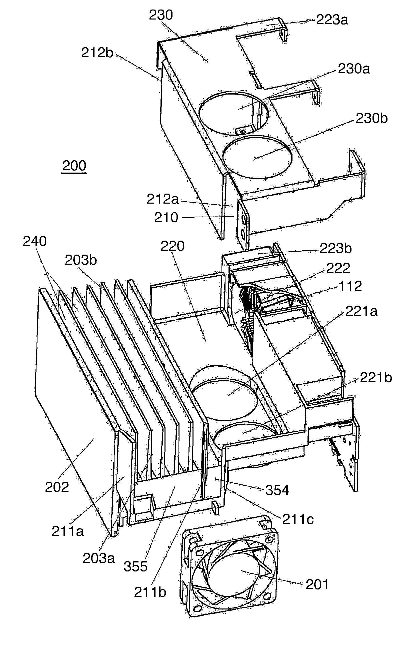
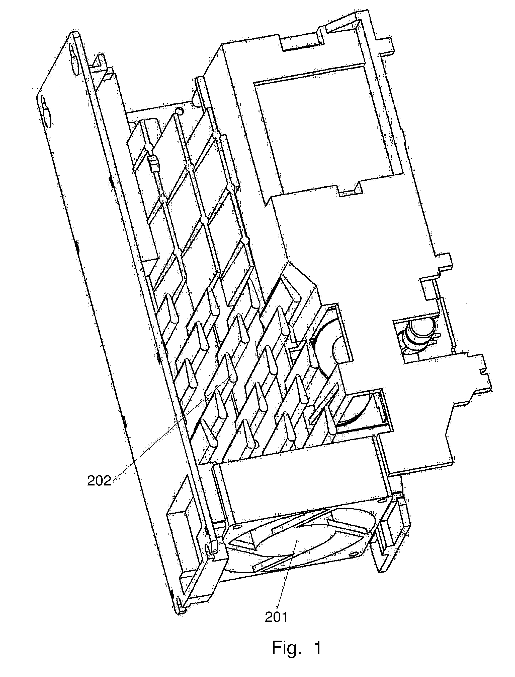
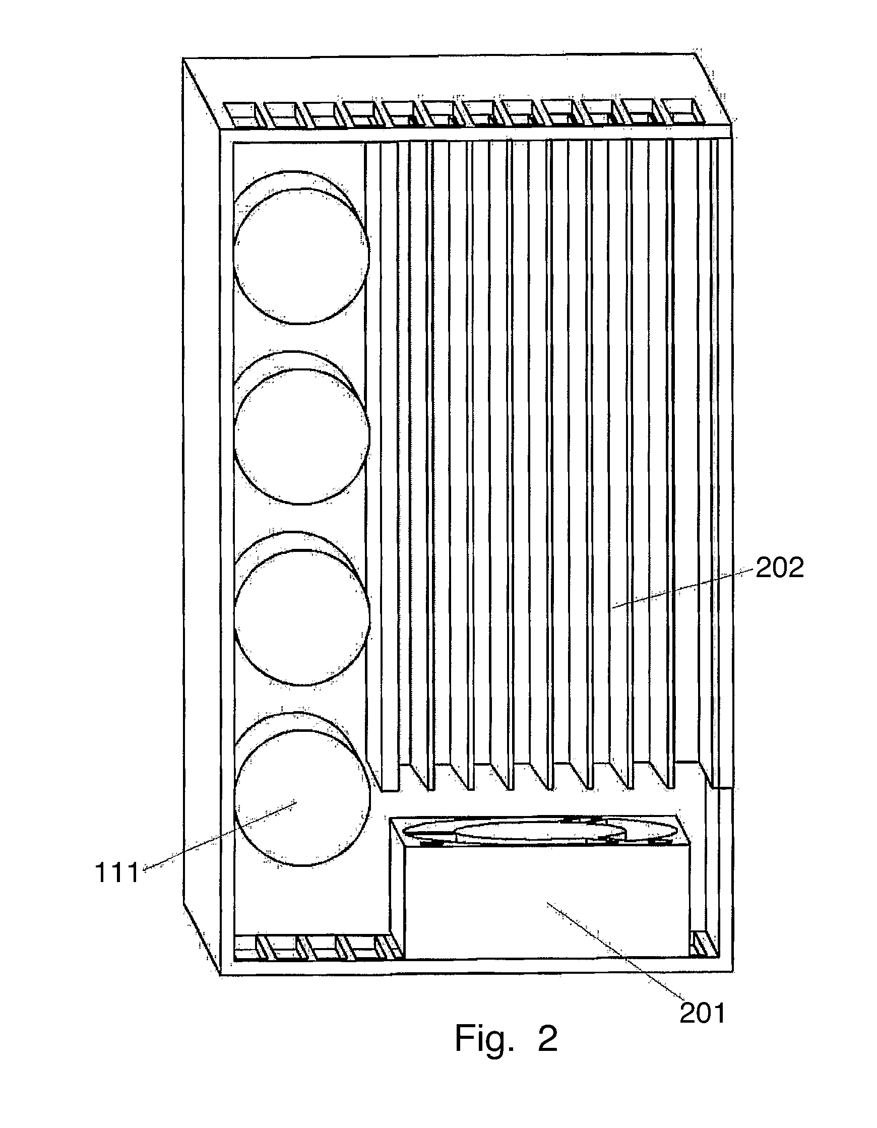
[0046]The first embodiment of the present invention is described by illustrating an example of the frequency converter used for driving a motor. FIG. 3 is a schematic view showing an electronic device according to the first embodiment of the present invention. Referring to FIG. 3, at least one first heat-generating element 110, such as Insulating Gate Bipolar transistor (IGBT) module consisted of a plurality of IGBT and metal oxide semiconductor field effect transistor, are mounted on the circuit board 100. The IGBT module may have single IGBT or a plurality of IGBTs separately packaged, or may further comprise other functional elements, such as a metal oxide semiconductor field effect transistor etc. The at least one first heat-generating element 110 is connected to a heat sink 202 so as to be cooled. The heat sink 202 can be formed by aluminum extrusion or aluminum casting. Second heat-generating elements, such as a plurality of capacitors 111a, 111b and a coil...

second embodiment

The Second Embodiment

[0063]The second embodiment of the present invention has substantially the same structure as that of the first embodiment except the separating member 220 and the conductive member 230. Therefore, the separating member 220 and the conductive member 230 of the second embodiment will mostly be described hereafter, and thereby omitting the same description with the first embodiment.

[0064]FIG. 6 is a schematic view showing an electronic device according to the second embodiment of the present invention.

[0065]Referring to FIG. 6, in the second embodiment of the present invention, the separating member 220 is formed with a rectangle box shape, which is substantially the same as that of the second airflow passage of the first embodiment. Therefore, the separating member 220 has two functions: one is to separate a main body of the at least one second heat-generating element on the circuit boards 100 and 101 or at least one portion of the main body from the other element...

third embodiment

The Third Embodiment

[0067]The third embodiment of the present invention has the same structure as that of the first embodiment and the second embodiment except the bracket of the at least one first heat generating element and the separating member. Therefore, the bracket of the third embodiment will be described hereafter, and thereby omitting the same description with the first embodiment and the second embodiment.

[0068]FIG. 7A is a bottom view of the bracket 226 and the heat insulation member 224 of the frequency converter according to the third embodiment of the present invention, and FIG. 7B is a top view of the bracket 226 and the heat insulation member 224 of the frequency converter according to the third embodiment of the present invention.

[0069]Referring to FIGS. 7A and 7B, the heat insulation member 224 may integrally be formed with the separating member 220, i.e. the separating member 220 may be bent downward and extends on a side of the heat sink 202 to form a sidewall 22...


PUM


Abstract

The present invention provides a frequency converter for driving a motor, comprising: a circuit board, having at least one first heat-generating element mounted thereon; a heat sink, connected to the at least one first heat-generating element; a fan, facing the heat sink; and a bracket, for positioning the at least one heat-generating element relative to the heat sink and the circuit board. The frequency converter further comprises: a separating member for separating the at least one portion of the main body of the at least one second heat-generating element from the circuit board, so as to prevent the cooling air guided to the at least one second heat-generating element from flowing to the circuit board; an airflow guiding member placed between the fan and the heat sink, for guiding the cooling air flowed from the fan to the heat sink and the at least one second heat-generating element respectively; and a flow guiding gate guiding the airflow from the fan to the heat sink, and dispensing more airflow to flow through the region corresponding to the at least one first heat-generating element.

Description

CROSS REFERENCE TO RELATED APPLICATIONS[0001]This application is entitled to the benefit of and incorporates by reference essential subject matter disclosed in International Patent Application No. PCT / DK2007 / 000542 filed on Dec. 10, 2007 and Chinese Patent Application No. 200610165938.4 filed Dec. 11, 2006.TECHNICAL FIELD[0002]The present invention relates to an electronic device and a frequency converter of motor for controlling the rotating speed of a motor, in particular, to an improvement of the cooling method of a frequency converter of motor, which can effectively isolate and cool a heat-generating member on a circuit board, so as to reduce its temperature and prevent the other elements on the circuit board from being contaminated by the impurity in cooling air. Such frequency converter of motor can be an alternating current (AC) or direct current (DC) frequency converter of motor.BACKGROUND ART[0003]FIG. 1 is a schematic view showing a non-closed type forced cooling frequency...

Claims


Application Information

Patent Timeline
Patent Type & Authority Applications(United States)
IPC IPC(8): H05K7/20
CPCH05K7/20918H02M7/003
Inventor ZHENG, LIREDZEPOVIC, ELVIRANDERSEN, HENRIK ROSENDAL
Owner DANFOSS DRIVES
Why Eureka
Try Eureka