Heat sink, laser apparatus provided with such heat sink, and laser stack apparatus

a laser apparatus and heat sink technology, which is applied in semiconductor lasers, lighting and heating apparatus, semiconductor/solid-state device details, etc., can solve the problems of high thermal conductivity and thermal expansion coefficient nearly equal to the coefficient of laser diodes, and the degradation of laser diodes' characteristics, so as to reduce the stress strain on a heat generating body

Inactive Publication Date: 2010-08-12
HAMAMATSU PHOTONICS KK
View PDF3 Cites 10 Cited by
  • Summary
  • Abstract
  • Description
  • Claims
  • Application Information

AI Technical Summary

Benefits of technology

[0005]The present invention has been accomplished in view of the above-described circumstances, and an object of the invention is to provide a heat sink capable of reducing the stress strain on a heat generating body, and a laser apparatus and laser stack apparatus therewith.

Problems solved by technology

The reason for it is that if the laser diode and the heat sink thermally expand and contract with temperature change caused by heat generation during driving of the laser diode or by repetitive activation and deactivation of the laser diode, the difference between the coefficients of thermal expansion of the two materials will give rise to stress strain in the laser diode and result in degradation of characteristics of the laser diode.
However, materials having a high thermal conductivity and a coefficient of thermal expansion nearly equal to that of the laser diode are expensive, and production cost will be very high if the whole heat sink is made of such a material.

Method used


Image

  • Heat sink, laser apparatus provided with such heat sink, and laser stack apparatus
  • Heat sink, laser apparatus provided with such heat sink, and laser stack apparatus
  • Heat sink, laser apparatus provided with such heat sink, and laser stack apparatus

Examples


Embodiment Construction

[0021]An embodiment of the present invention will be described below in detail with reference to the accompanying drawings. The same elements will be denoted by the same reference symbols in the description of the drawings, without redundant description.

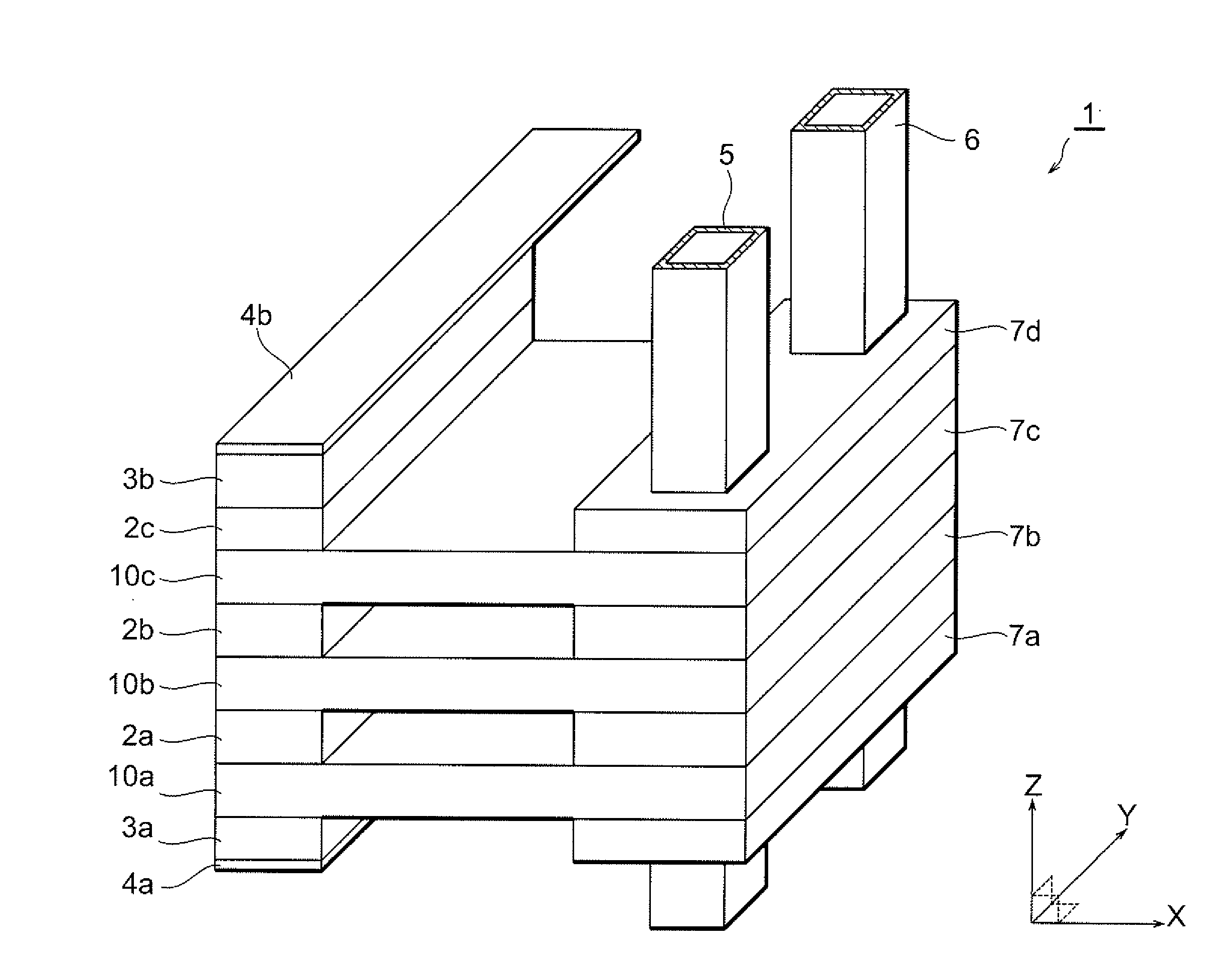
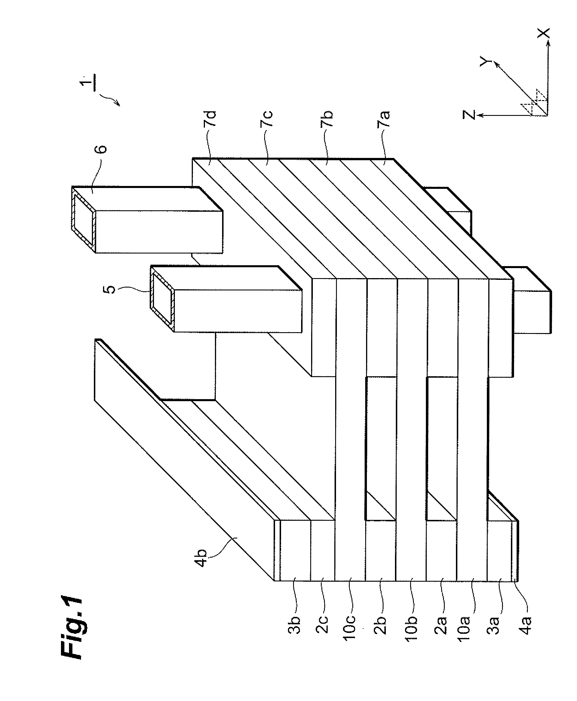
[0022]FIG. 1 is a perspective view showing a configuration of an embodiment of the laser stack apparatus according to the present invention. This laser stack apparatus 1 has three laser arrays 2a-2c, two copper plates 3a and 3b, two lead plates 4a and 4b, a supply tube 5, a discharge tube 6, four insulating members 7a-7d, and three heat sinks 10a-10c.

[0023]Each of the components will be described below. For convenience' sake of description, the positive direction of the Z-axis is taken up and the negative direction of the Z-axis is taken down in FIG. 1.

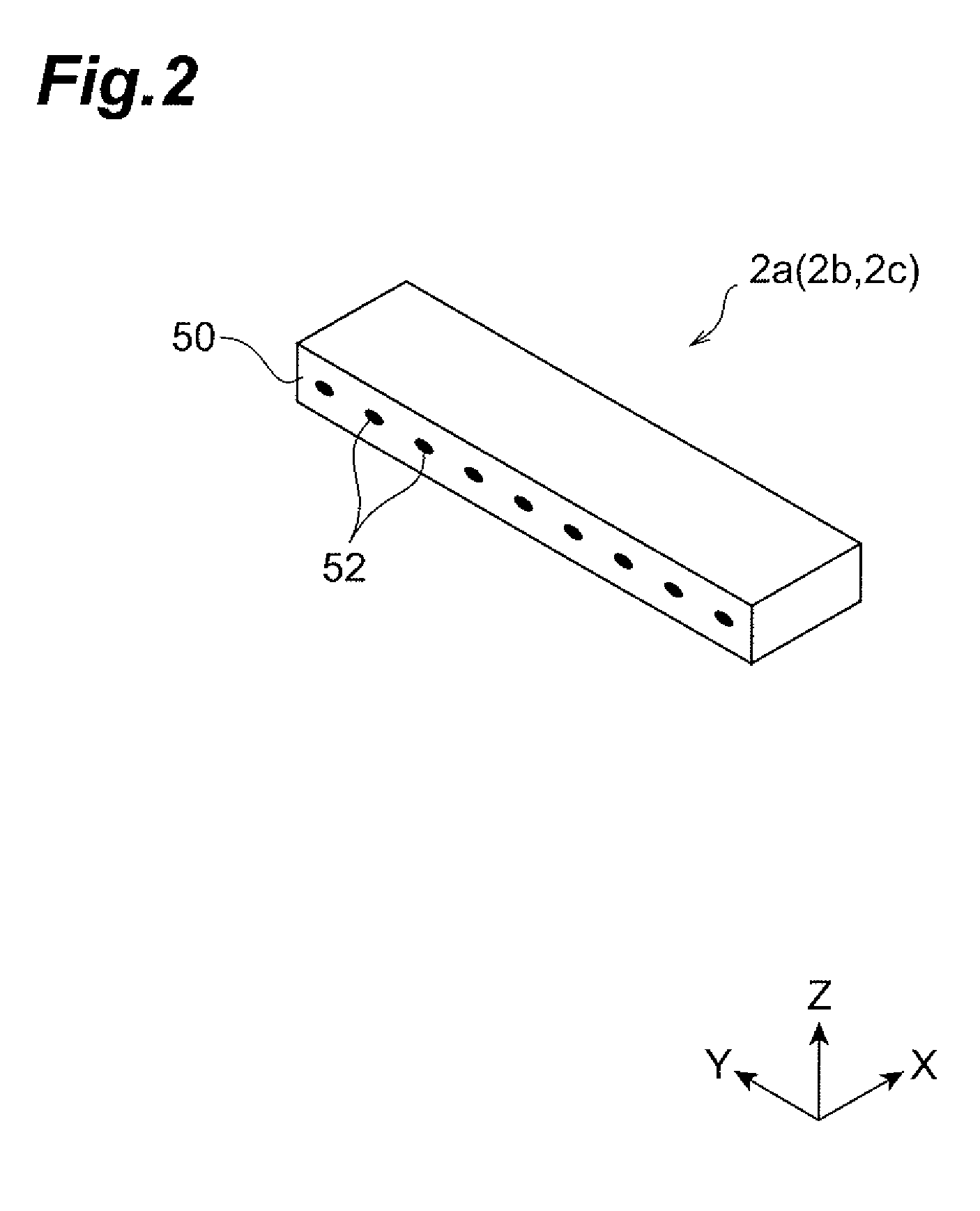
[0024]FIG. 2 is a perspective view showing a laser array 2a. The laser arrays 2b and 2c have the same structure as the laser array 2a. Each laser array is a semiconductor laser elemen...


PUM


Abstract

A heat sink has a first flat plate, a partition plate, and a second flat plate. The first flat plate has an upper surface in which a first recess is formed. The second flat plate has a lower surface in which a second recess is formed, and an upper surface on which a semiconductor laser element is mounted. These recesses form a part of a refrigerant channel. The partition plate has a lower surface covering the first recess, an upper surface covering the second recess, and at least one through hole having the first recess communicated with the second recess. The first flat plate and the second flat plate both have a first coefficient of thermal expansion. The partition plate has a second coefficient of thermal expansion lower than the first coefficient of thermal expansion.

Description

TECHNICAL FIELD[0001]The present invention relates to a heat sink used for cooling a heat generating body such as a semiconductor device, and to semiconductor laser apparatus and semiconductor laser stack apparatus using it.BACKGROUND ART[0002]In recent years, a water-cooling type heat sink is often used for effectively cooling a high-power laser diode. In order to increase the cooling efficiency, it is desirable to make the heat sink of a material with a high thermal conductivity. Furthermore, the material of the heat sink is preferably one having a coefficient of thermal expansion close to that of the laser diode. The reason for it is that if the laser diode and the heat sink thermally expand and contract with temperature change caused by heat generation during driving of the laser diode or by repetitive activation and deactivation of the laser diode, the difference between the coefficients of thermal expansion of the two materials will give rise to stress strain in the laser diod...

Claims


Application Information

Patent Timeline
Patent Type & Authority Applications(United States)
IPC IPC(8): H01S3/04F28F7/00
CPCH01L23/473H01S5/02264H01S5/02423H01S5/4018H01L2924/0002H01S5/4025H01L2924/00H01S5/02365
Inventor MIYAJIMA, HIROFUMIKAN, HIROFUMIWATANABE, NOBUOOOISHI, SATORUSUZUKI, NOBUTAKA
Owner HAMAMATSU PHOTONICS KK
Why Eureka
Try Eureka