Surface-plasmon-assisted optical frequency conversion

a surface plasmon and optical frequency conversion technology, applied in the direction of optical waveguide light guide, optical elements, instruments, etc., can solve the problems of limited choice of nonlinear optical materials suitable for use therein, and the power-conversion efficiency provided by those nonlinear optical materials might not be optimal, so as to facilitate efficient energy transfer and high power-conversion efficiency

Inactive Publication Date: 2010-08-12
ALCATEL-LUCENT USA INC +1
View PDF17 Cites 11 Cited by
  • Summary
  • Abstract
  • Description
  • Claims
  • Application Information

AI Technical Summary

Benefits of technology

[0007]Provided are various embodiments of an optical frequency converter that uses a nonlinear optical process to transfer energy between a surface-plasmon (SP) wave that is guided along an electrically conducting strip and a light beam that is guided along an optical waveguide whose core is adjacent to the electrically conducting strip. The optical frequency converter has a periodic structure that spatially modulates the nonlinear susceptibility of the waveguide core with a spatial period that is related to a momentum mismatch in the nonlinear optical process. The spatial modulation provides quasi-phase matching for the SP wave and the light beam and facilitates efficient energy transfer between them. Surface-induced enhancement of the electric field in the SP wave near the electrically conducting strip enables a representative optical frequency converter of the invention to advantageously have a relatively high power-conversion efficiency.

Problems solved by technology

One problem with optical frequency converters is that the choice of nonlinear optical materials suitable for use therein is limited.
Furthermore, power-conversion efficiency provided by those nonlinear optical materials might not be optimal.

Method used


Image

  • Surface-plasmon-assisted optical frequency conversion
  • Surface-plasmon-assisted optical frequency conversion
  • Surface-plasmon-assisted optical frequency conversion

Examples


Embodiment Construction

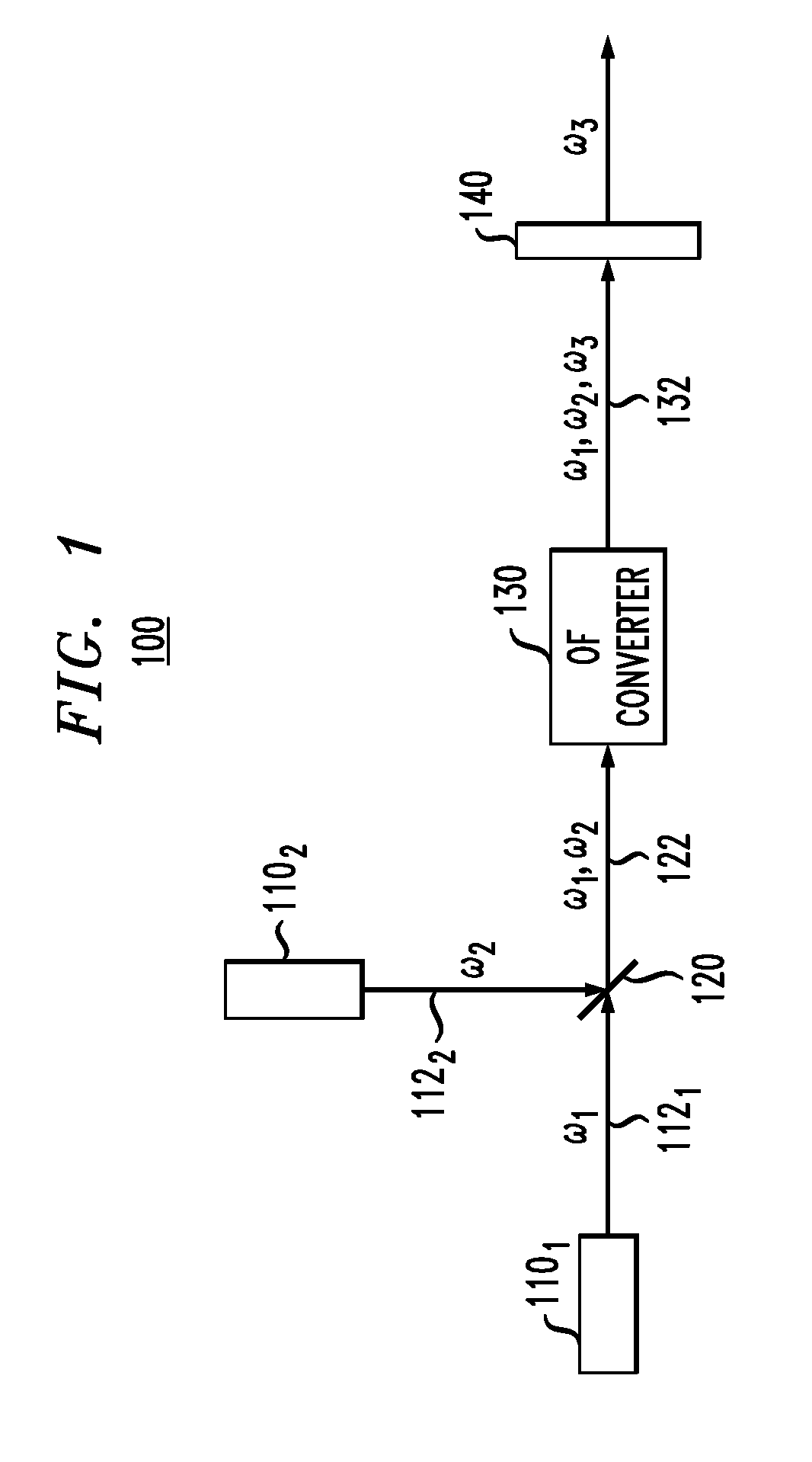
[0014]FIG. 1 shows a block diagram of an optical generator 100 according to one embodiment of the invention. Generator 100 has light sources 1101 and 1102 that generate light beams 1121 and 1122 having optical frequencies ω1 and ω2, respectively. A beam combiner 120 combines beams 1121 and 1122 and directs a resulting combined beam 122 to an optical frequency (OF) converter 130. Converter 130 has a nonlinear optical medium (not explicitly shown in FIG. 1), where optical frequencies ω1 and ω2 of beam 122 interact to produce at least one additional optical frequency, which is labeled ω3. An output light beam 132 produced by converter 130 generally has the original frequencies ω1 and ω2 and at least one new frequency ω3. An (optional) optical filter 140 that receives light beam 132 from converter 130 transmits frequency ω3 while blocking the other optical frequencies contained in that light beam.

[0015]The relationship between frequencies ω1, ω2, and ω3 depends on the type of nonlinear ...


PUM


Abstract

An optical frequency converter that uses a nonlinear optical process to transfer energy between a surface-plasmon (SP) wave that is guided along an electrically conducting strip and a light beam that is guided along an optical waveguide whose core is adjacent to the electrically conducting strip. The optical frequency converter has a periodic structure that spatially modulates the nonlinear susceptibility of the waveguide core with a spatial period that is related to a momentum mismatch in the nonlinear optical process. The spatial modulation provides quasi-phase matching for the SP wave and the light beam and enables efficient energy transfer between them.

Description

BACKGROUND OF THE INVENTION[0001]1. Field of the Invention[0002]The present invention relates to nonlinear optical devices and, more specifically, to optical frequency converters.[0003]2. Description of the Related Art[0004]This section introduces aspects that may help facilitate a better understanding of the invention(s). Accordingly, the statements of this section are to be read in this light and are not to be understood as admissions about what is in the prior art or what is not in the prior art.[0005]As used herein, the term “optical frequency conversion” refers to a process that converts light of one frequency (wavelength) into light of another frequency (wavelength). An optical frequency converter might use a nonlinear optical medium, in which one or more nonlinear optical processes transfer energy from one or more pump frequencies to a new (converted) frequency. The relevant nonlinear optical processes might include, but are not limited to, second-harmonic generation, sum-fre...

Claims


Application Information

Patent Timeline
Patent Type & Authority Applications(United States)
IPC IPC(8): G02B6/12
CPCB82Y20/00G02B6/1226G02F1/0356G02F1/3532G02F1/3534G02F2203/10G02F2001/3548G02F2201/066G02F2201/127G02F2202/20G02F1/3536G02F1/3548
Inventor BLUMBERG, GIRSHCHOWDHURY, AREF
Owner ALCATEL-LUCENT USA INC
Why Eureka
Try Eureka