
Self-cleaning susceptor for solar cell processing

a solar cell and susceptor technology, applied in the direction of chemical vapor deposition coating, metal material coating process, coating, etc., can solve the problem that solar cell substrates are increasingly prone to breakage in process chambers, and the system that uses lift pins to move substrates cannot readily remove broken substrates

Inactive Publication Date: 2010-08-12
APPLIED MATERIALS INC
View PDF10 Cites 177 Cited by
  • Summary
  • Abstract
  • Description
  • Claims
  • Application Information

AI Technical Summary

Benefits of technology

[0007]In one embodiment of the invention, a susceptor for an apparatus for processing a substrate is provided. The susceptor includes a plurality of segments aligned to form a substrate support surface, each segment having one or more flat surfaces for supporting the substrate, and an opening that extends along an axis of rotation. The susceptor also includes a plurality of rotatable shafts, each shaft positioned in the opening of one of the segments.
[0008]In another embodiment of the invention, an apparatus for processing a substrate is provided. The apparatus includes a processing chamber and a susceptor located within the chamber. The susceptor includes a plurality of segments aligned to form a substrate support surface, each segment having one or more flat surfaces for supporting the substrate, and an opening that extends along an axis of rotation. The susceptor also includes a plurality of rotatable shafts, each shaft positioned in the opening of one of the segments.
[0009]In yet another embodiment of

Problems solved by technology

The high market growth rate in combination with the need to substantially reduce solar electricity costs has resulted in a number of serious challenges for silicon substrate production development for photovoltaics.
Thus, solar cell substrates are increasingly prone to breakage in process chambers.
However, systems that use lift pins to move substrates cannot readily remove broken substrates.

Method used


Image

  • Self-cleaning susceptor for solar cell processing
  • Self-cleaning susceptor for solar cell processing
  • Self-cleaning susceptor for solar cell processing

Examples


Embodiment Construction

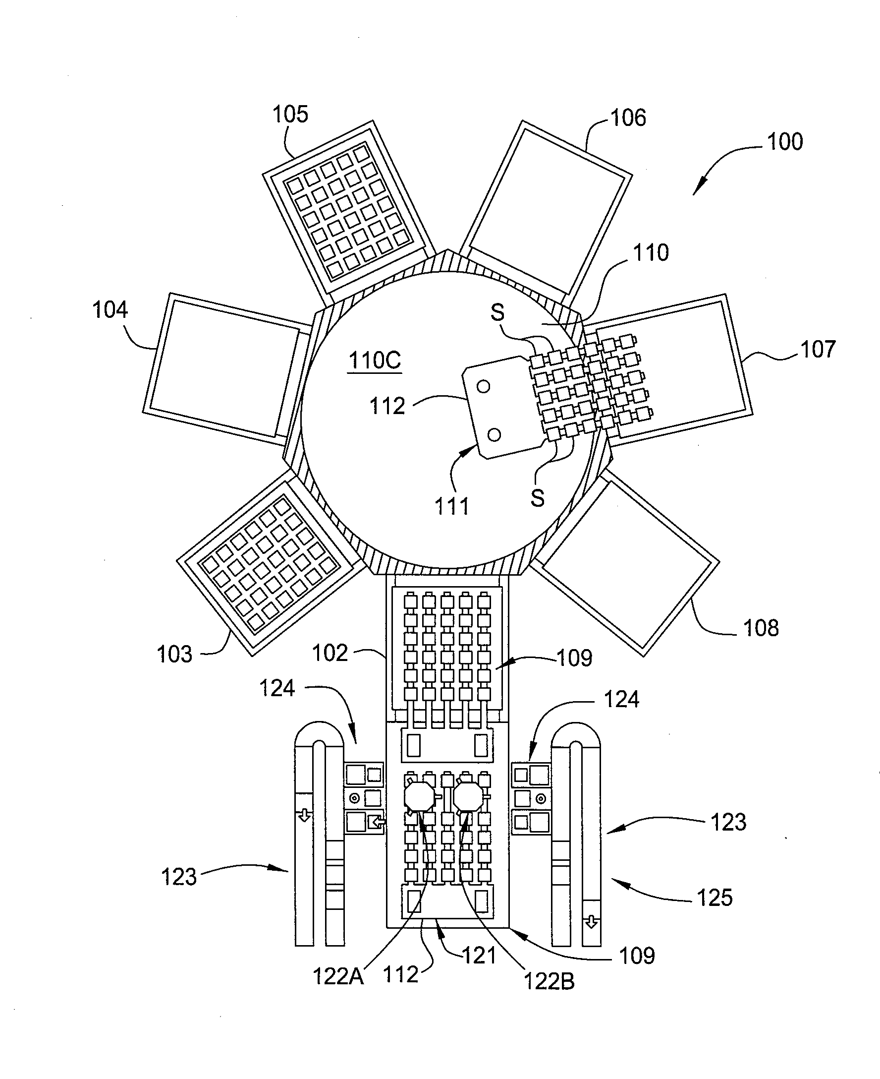
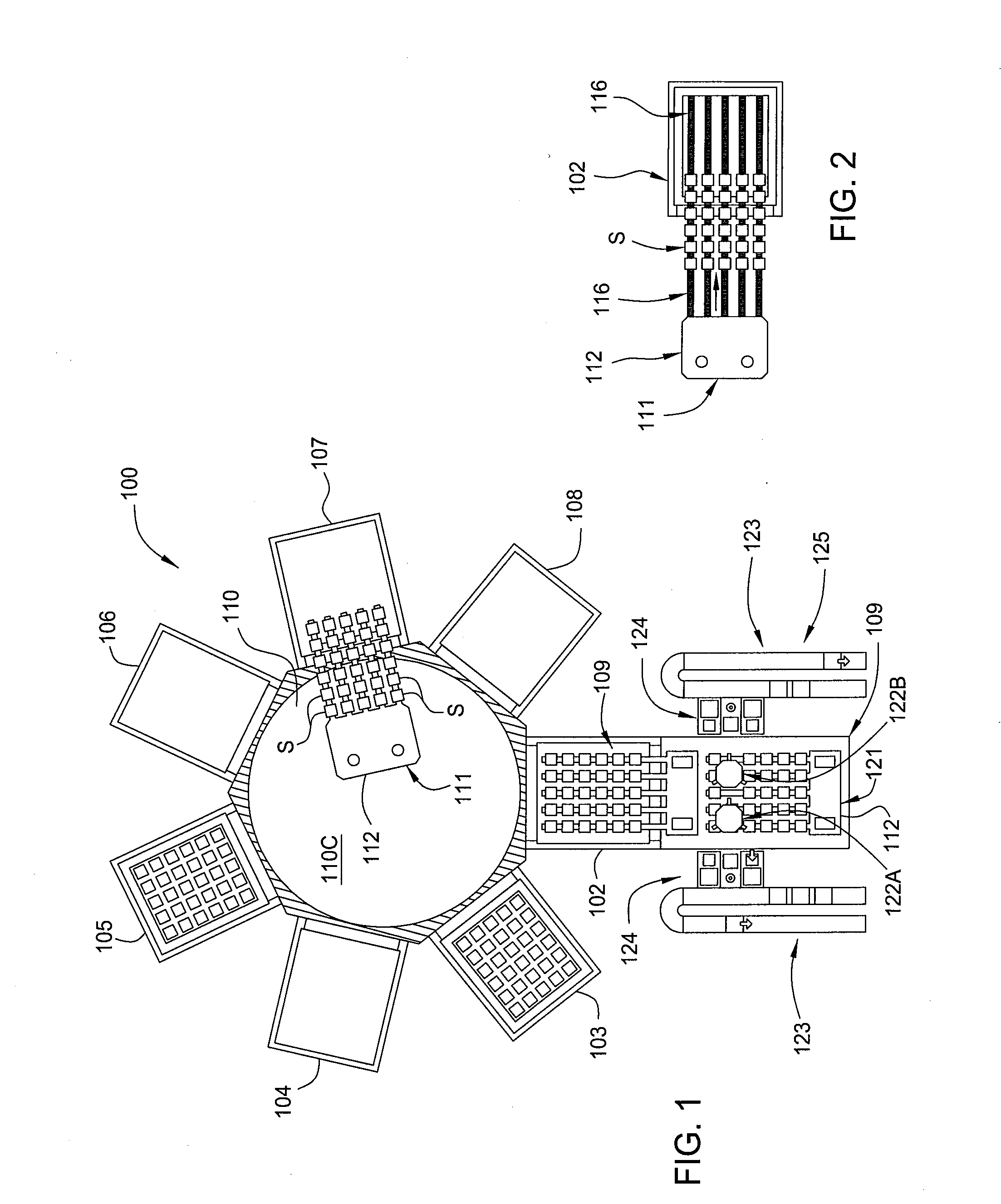
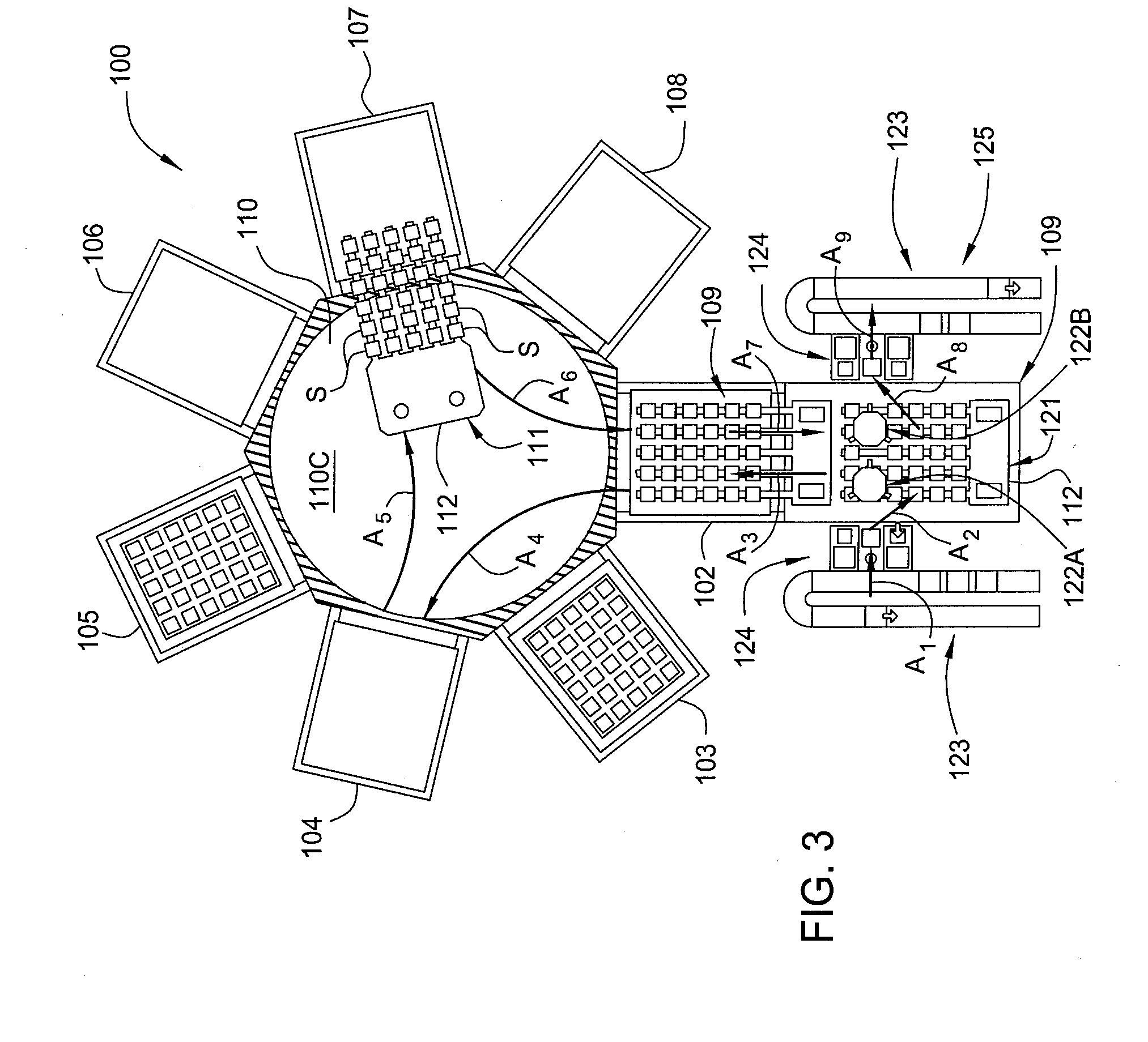
[0020]Embodiments of the present invention generally provide a susceptor for processing a substrate that may be used in various chambers, systems, and processing tools, such as a cluster tool, for in-situ processing of a film stack used to form regions of a solar cell device. In one configuration, the film stack formed on each of the substrates in the batch contains one or more passivating or dielectric layers and one or more metal layers that are deposited and further processed within various processing chambers contained in the substrate processing system. The processing chamber has a susceptor for supporting and processing the substrates. In some embodiments of the invention, the susceptor may also transport substrates in and out of processing chambers (FIGS. 7A-7C).

[0021]The processing chambers may be, for example, physical vapor deposition (PVD) or sputtering chambers, plasma enhanced chemical vapor deposition (PECVD) chambers, hot wire chemical vapor deposition (HWCVD) chamber...


PUM

PropertyMeasurementUnit
Volumeaaaaaaaaaa

Abstract

An apparatus and method for processing substrates are provided. In one embodiment, a susceptor for an apparatus for processing a substrate includes a plurality of segments aligned to form a substrate support surface, each segment having one or more flat surfaces for supporting the substrate, and an opening that extends along an axis of rotation. The susceptor also includes a plurality of rotatable shafts, each shaft positioned in the opening of one of the segments. The method of processing a batch of substrates includes transferring at least one substrate in the batch into a processing chamber and onto a susceptor, processing the at least one substrate within the chamber, transferring the at least one substrate out of the processing chamber, and removing debris from the substrate support surface by rotating the segments to dump any debris on the substrate support surface onto a chamber floor where it will remain during further processing.

Description

BACKGROUND OF THE INVENTION[0001]1. Field of the Invention[0002]Embodiments of the invention generally relate to an apparatus and a method for forming a solar cell device. Some embodiments are particularly useful for fabrication of crystalline silicon solar cells.[0003]2. Description of the Related Art[0004]Photovoltaics (PV) or solar cells are devices which convert sunlight into direct current (DC) electrical power. A typical PV cell includes a p-type silicon wafer, substrate, or sheet typically less than about 0.3 mm thick with a thin layer of an n-type silicon material disposed on top of the p-type substrate. The generated voltage, or photo-voltage, and generated current by the photovoltaic device are dependent on the material properties of the substrate and p-n junction, the interfacial properties between deposited layers, and the surface area of the device. When exposed to sunlight (consisting of energy from photons), the p-n junction of the PV cell generates pairs of free elec...

Claims


Application Information

Patent Timeline
IPC IPC(8): C23C16/458
CPCC23C16/4401C23C16/54C23C16/4583
Inventor BORDEN, PETER
Owner APPLIED MATERIALS INC
Learn More