Automated transport control system

a technology of automatic control system and transport control, applied in the direction of electric controllers, total factory control, programme control, etc., can solve the problems of any substantial portion of a complete system or a complete system being broken, and achieve the effect of limiting the effect of failures and rapid operation

Inactive Publication Date: 2010-08-12
AUTRAN CORP
View PDF2 Cites 9 Cited by
  • Summary
  • Abstract
  • Description
  • Claims
  • Application Information

AI Technical Summary

Benefits of technology

[0018]Another feature relates to use of separate processors to perform different functions, so as to limit the effect of failures. A drive processor is used to develop drive data for controlling drive of the carrier. Another processor is used for sending carrier ahead data back to a MCU behind, another for sending outgoing merge data to a MCU ahead and another for sending incoming merge data to a MCU behind. Each processor may be designed, constructed and tested to insure its performance of its limited function. A temporary failure of the drive processor of one MCU should have limited effect on the critical functions of the latter three processors and should have limited effect on the speed of a carrier. If a carrier is moving at 130 feet / second and the length of the assigned region of a MCU is 40 feet, a failure of the drive processor of one MCU may result in a lapse about 0.3 seconds in the sending of drive data to the carrier and in coasting of the carrier for 0.3 seconds. There may be a reduction in speed but it should be small and, if other processors are working properly, the processor of the next MCU ahead can be expected to restore control after 0.3 seconds.
[0019]A further feature relates to the rapid performance of operations to obtain quick responses to changes in conditions. In an illustrated embodiment, the drive processor is operated in response to pulses which may be supplied at a 100 Hz rate, for example, so as to respond in 0.01 seconds to a change in conditions.

Problems solved by technology

Using security safeguards, a central or other computer may exercise control of MCUs in the event of power failures or other problems.
However, the system requires no central or any other computer that can malfunction and cause a breakdown of a complete system or any substantial portion of a complete system.

Method used


Image

  • Automated transport control system
  • Automated transport control system
  • Automated transport control system

Examples


Embodiment Construction

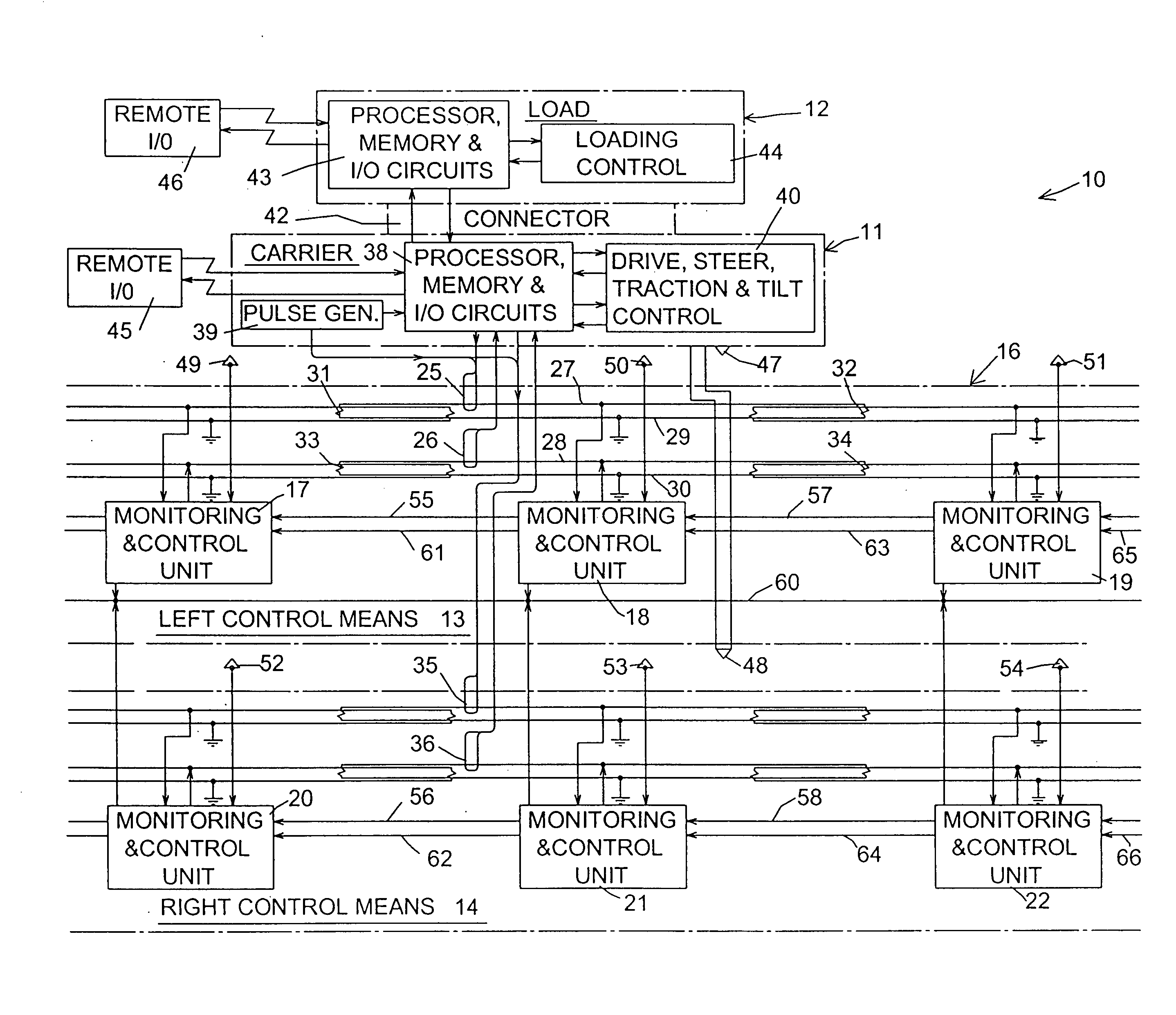
[0034]FIG. 1 illustrates portions of a control system 10 of the invention. The system 10 is designed for use along guideways for automated control of carriers moving there-along. The guideways might be like conventional roadways and the carriers might be vehicles such as automobiles moving along such roadways. However, the invention is particularly designed for use along elevated or otherwise dedicated guideways that support carriers each carrying a load such as a passenger cabin, a cargo container or pallet or a car, light truck, SUV or other vehicle. My U.S. Pat. Nos. 5,590,604, 5,706,735, 5,979,334 and 6,622,635 provide examples of such guideways and carriers. (Carriers are referred to as “carrier vehicles” in my patents). My patents also provide examples of important features including control of steering, control of traction, control of tilt of loads, transfer of loads to and from carriers and weighing of carriers. The disclosures of my said patents are incorporated by referenc...


PUM


Abstract

Each load-carrier of a system is always controlled by one of a series of MCUs (monitoring and control units) that are assigned to contiguous regions along guideways. Each carrier is slowed down to maintain a safe distance behind a carrier ahead, or to avoid collision with another carrier when approaching a merge point of a convergent Y-junction or when otherwise desirable. Distance measurements take into account the lengths of carriers and of assigned regions and the counts of speed pulses sent to MCUs since entry of carriers into their respective regions. For merge control, arrival data are developed that include the times and speeds to and at arrival of two carriers at a merge point. Through repeated comparisons of arrival data developed from one carrier with arrival data previously developed and stored as to the other carrier, the one carrier is gradually slowed down as necessary to avoid a collision.

Description

[0001]A claim is made for the priority benefits of Provisional Application No. 61 / 206,919, entitled “AUTOMATED TRANSPORT CONTROL SYSTEM”, filed Feb. 4, 2009.BACKGROUND OF THE INVENTION[0002]This invention relates to improvements upon prior automated transport systems, particularly those disclosed in my U.S. Pat. Nos. 5,590,603, 5,590,604, 5,598,783, 5,706,735, 5,979,334, 6,082,268, 6,237,500 and 6,622,635 and in references cited therein.SUMMARY OF THE INVENTION[0003]This invention is part of an evolutionary process that has occurred during many years of my work on the design of automated transport systems that might help solve a myriad of transportation problems. My issued disclose systems in which loads are moved on carriers (referred to as “carrier vehicles” in my patents) that operate on electrified guideways. They include disclosures of control systems that have a number of advantageous features. An object of this invention is to improve upon such control systems.[0004]A more sp...

Claims


Application Information

Patent Timeline
Patent Type & Authority Applications(United States)
IPC IPC(8): G05B15/02
CPCG05B2219/31003G05B19/41895Y02P90/02Y02P90/60
Inventor LUND, VAN METRE
Owner AUTRAN CORP
Why Eureka
Try Eureka