Eureka AIR delivers breakthrough ideas for toughest innovation challenges, trusted by R&D personnel around the world.

Method and Apparatus for Examining Ion-Conductive Electrolyte Membrane

a technology of electrolyte membrane and ion-conductive electrolyte, which is applied in the direction of instruments, cell components, sustainable manufacturing/processing, etc., can solve the problems of reducing the electric power generation capacity, the uniform oxygen ion conductivity of the electrolyte membrane in every region cannot be examined, and the atmosphere does not give the location of the defect, etc., to achieve the effect of increasing the hydrogen ion conductivity of the ion-conductive electrolyte membran

Active Publication Date: 2010-08-19
ATSUMITEC CO LTD
View PDF3 Cites 5 Cited by
  • Summary
  • Abstract
  • Description
  • Claims
  • Application Information

AI Technical Summary

Benefits of technology

[0007]The present invention has been made in view of the problems as mentioned above. The primary object of the present invention is to provide an examination method and apparatus capable of more accurately examining an ion-conductive electrolyte membrane.
[0008]In order to achieve the above object, in a method for examining an ion-conductive electrolyte membrane according to the present invention, a detection membrane including a thin film layer is joined to a first surface of the ion-conductive electrolyte membrane, and hydrogen gas is supplied to a space facing the first surface of the ion-conductive electrolyte membrane to hydrogenate the detection membrane. Thereafter, oxygen gas is supplied to a space facing a second surface of the ion-conductive electrolyte membrane. If the ion-conductive electrolyte membrane has a defect, oxygen gas leaks from the second surface to the first surface of the ion-conductive electrolyte membrane through the defect, so that the thin film layer is dehydrogenated in a portion near the defect and varies in electric resistance. Thus, whether or not a defect exists can be examined quickly with high accuracy by observing a change in electric resistance of the thin film layer which results from the dehydrogenation.

Problems solved by technology

In such solid oxide fuel cell, if the electrolyte membrane constituting part of the membrane electrode assembly has a defect, such as a pin hole or a crack, gas leaks through the electrolyte membrane, resulting in a reduction in electric power generation capacity.
If, for example hydrogen gas is supplied to a space facing one side of the electrolyte membrane, such defect allows the hydrogen gas to leak through it to the other side of the electrolyte membrane.
In addition, detection of leaked hydrogen gas in an atmosphere does not give the location of the defect.
In addition, whether or not the electrolyte membrane has uniform oxygen ion conductivity in every region cannot be examined by this measurement.

Method used


Image

  • Method and Apparatus for Examining Ion-Conductive Electrolyte Membrane
  • Method and Apparatus for Examining Ion-Conductive Electrolyte Membrane
  • Method and Apparatus for Examining Ion-Conductive Electrolyte Membrane

Examples


first embodiment

[0038]First, as a method for examining an ion-conductive electrolyte membrane according to the present invention, a method for examining whether or not an ion-conductive electrolyte membrane has a defect, such as a pin hole or a crack, will be described with reference to FIGS. 1 to 3.

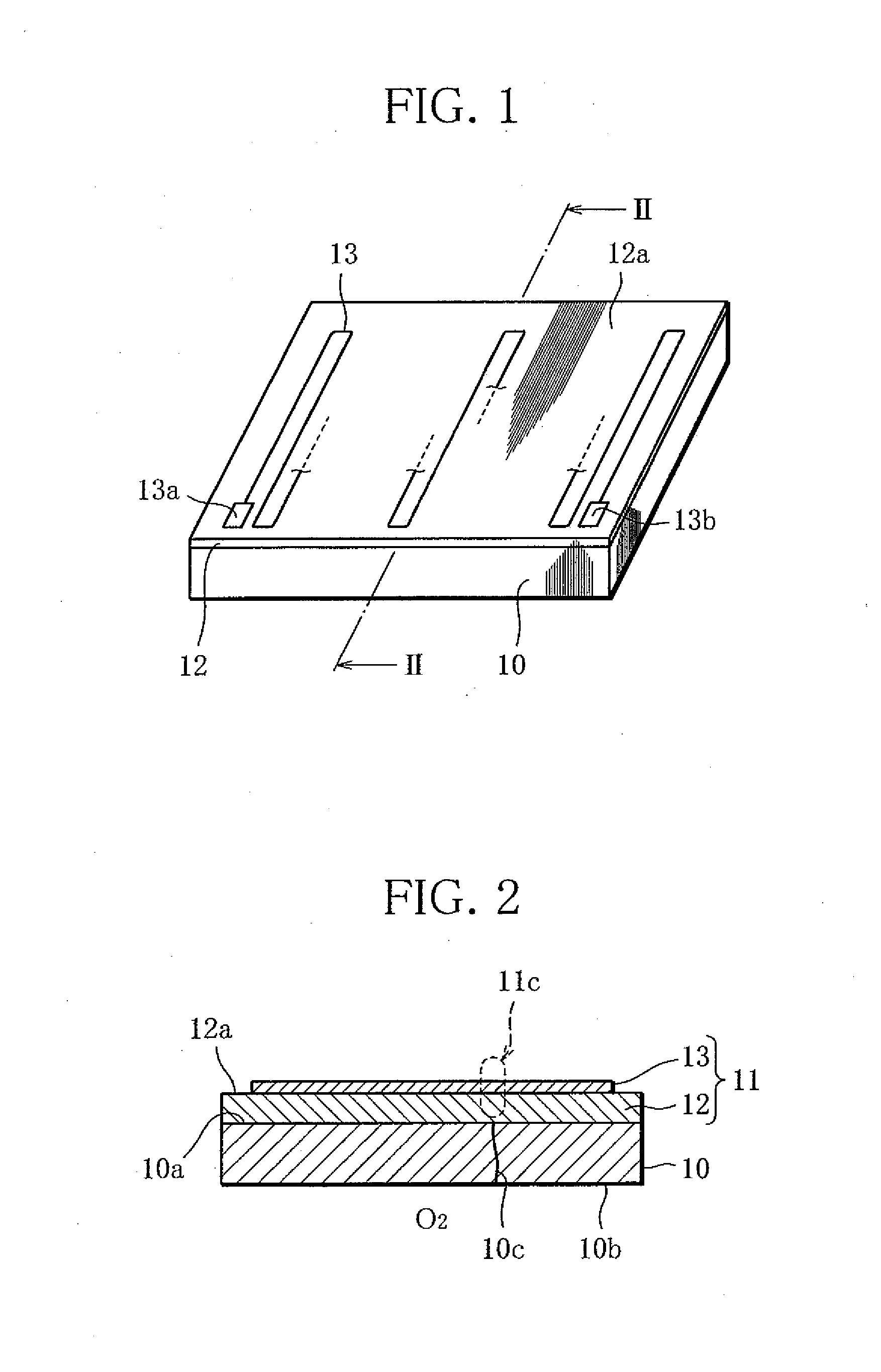
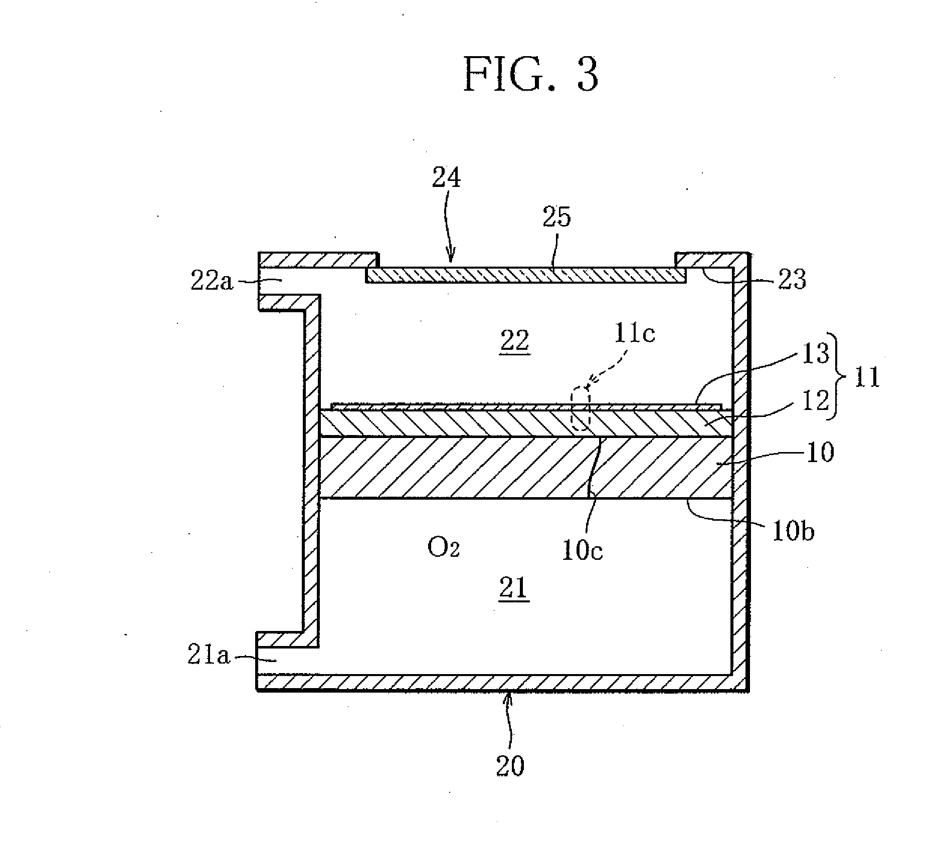
[0039]FIG. 1 is a perspective view showing an electrolyte membrane to be examined and a detection membrane joined to the electrolyte membrane. FIG. 2 is a cross-sectional view of the electrolyte membrane, etc. taken along line II-II in FIG. 1, and FIG. 3 is a schematic diagram showing an example of how the electrolyte membrane, etc. shown in FIG. 1 are arranged in a container to conduct examination.

[0040]As shown in FIGS. 1 and 2, a detection membrane 11, equal in planar shape to an electrolyte membrane 10, comprises a catalyst layer 12 and a thin film layer 13. The catalyst layer 12 is joined to a first surface 10a constituting one side of the electrolyte membrane 10, and the thin film layer 13 is form...

third embodiment

[0058]Next, as a method for examining an ion-conductive electrolyte membrane according to the present invention, a method for examining an ion-conductive electrolyte membrane on oxygen ion conductivity will be described with reference to FIGS. 7 to 11.

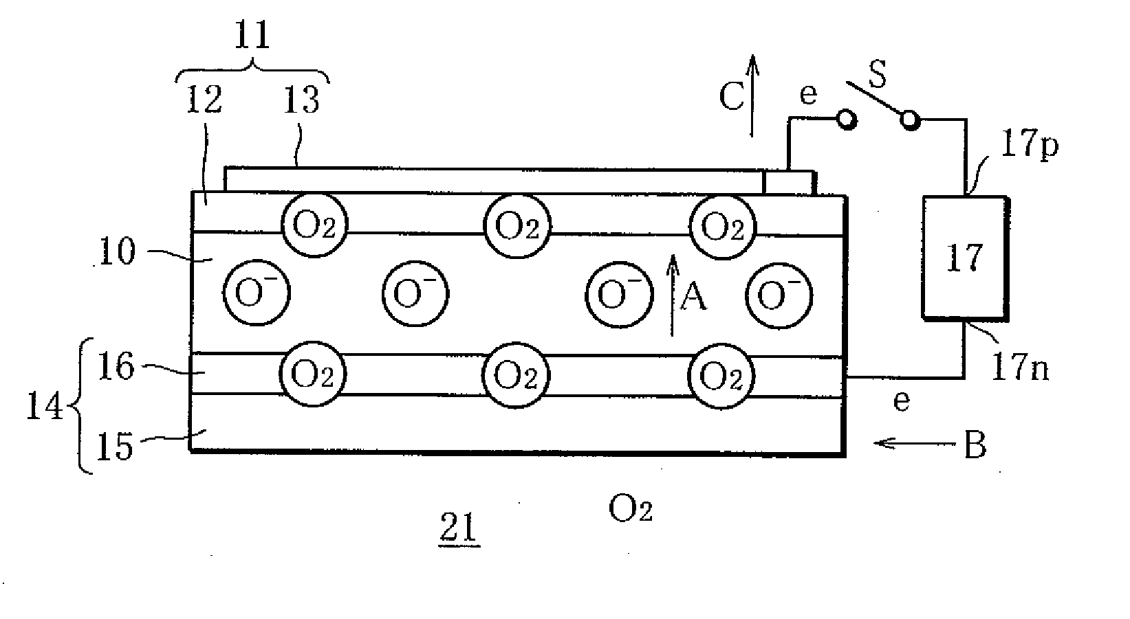
[0059]FIG. 7 is a perspective view showing an electrolyte membrane to be examined, with a detection membrane and an air electrode each joined to the electrolyte membrane. FIG. 8 is a schematic cross-sectional view showing the electrolyte membrane, air electrode and detection membrane. FIG. 9 is a schematic diagram showing an example of how a power supply circuit is connected between the air electrode and the detection membrane to examine the electrolyte membrane on oxygen ion conductivity, and also giving an explanation of the oxygen ion conductivity of the electrolyte membrane. FIG. 10 is a diagram showing how the resistance of thin film layers is measured by such circuit. FIG. 11 is a schematic diagram showing an example of how an el...

fourth embodiment

[0072]Next, as a method and apparatus for examining an ion-conductive electrolyte membrane according to the present invention, an examination method and apparatus capable of conducting examination of an ion-conductive electrolyte membrane for defects and examination thereof on oxygen ion conductivity in a continuous process will be described with reference to the drawings referred to in the explanation of the above embodiments.

[0073]As shown in FIG. 11, an examination apparatus 30 according to this embodiment is similar in structure to the third embodiment, and examines an electrolyte membrane 10 as shown in FIGS. 7 and 8. Specifically, the examination apparatus 30 comprises a container 20, a power supply circuit 17, a heater Ht, a switch S and an ohmmeter M, as shown in FIGS. 9 to 11. Inside the container 20, a first space 21 (facing an air electrode) 21 and a second space 22 are separated by the electrolyte membrane 10. Heated by the heater Ht, the electrolyte membrane 10 comes to...


PUM

PropertyMeasurementUnit
thickaaaaaaaaaa
thicknessaaaaaaaaaa
temperatureaaaaaaaaaa

Abstract

A detection membrane is joined to a first surface of an electrolyte membrane. After the detection membrane is hydrogenated, oxygen is supplied to a space facing a second surface of the electrolyte membrane. If the electrolyte membrane has a defect, oxygen leaks to the first surface, resulting in a change in resistance of the detection membrane owing to dehydrogenation of the detection membrane. The defect is recognized by this change. An air electrode is joined to the second surface, and an electric circuit is connected between the detection membrane and the air electrode. After hydrogenating the detection membrane and ionizing oxygen supplied to a space facing the air electrode, oxygen ions permeate through the electrolyte membrane and dehydrogenate the detection membrane. Uniformity of the oxygen ion conductivity is examined by measuring resistance of the detection membrane, which varies depending on the amount of oxygen ions, for each region.

Description

TECHNICAL FIELD[0001]The present invention relates to a method and apparatus for examining an ion-conductive electrolyte membrane.BACKGROUND ART[0002]An ion-conductive electrolyte membrane (hereinafter, sometimes referred to simply as “electrolyte membrane”) is used in a fuel cell, for example, and an oxygen ion-conducive electrolyte membrane is used in a membrane electrode assembly of a solid oxide fuel cell, for example. Such membrane electrode assembly is constructed by joining a fuel electrode (hydrogen electrode) to one side of a solid oxide electrolyte membrane which is an electrolyte membrane, and an air electrode (oxygen electrode) to the other side. In the solid oxide fuel cell having such membrane electrode assembly, hydrogen or carbon monoxide is supplied to the fuel electrode while oxygen or air is supplied to the air electrode. With the membrane electrode assembly heated, oxygen gains electrons at the air electrode to form oxygen ions. The oxygen ions permeate through t...

Claims


Application Information

Patent Timeline
Patent Type & Authority Applications(United States)
IPC IPC(8): B32B37/02G01N27/62
CPCG01N27/20Y02E60/525H01M8/04104H01M8/04261H01M8/04641H01M8/04783H01M8/1246H01M8/1253H01M8/126H01M2300/0071H01M2300/0074H01M2300/0077H01M2300/0094Y02E60/521H01M8/04089H01M8/04197Y02P70/50Y02E60/50
Inventor UCHIYAMA, NAOKI
Owner ATSUMITEC CO LTD
Why Eureka
Eureka Blog
Learn More