Aircraft based non-dedicated special mission pod mounting apparatus

a technology for aircraft-based special missions and mounting apparatus, which is applied in the direction of aircraft accessories, fuselages, military adjustment, etc., can solve the problems of unaddressed and ongoing needs

Active Publication Date: 2010-08-19
1281329 ALBERTA
View PDF18 Cites 16 Cited by
  • Summary
  • Abstract
  • Description
  • Claims
  • Application Information

AI Technical Summary

Benefits of technology

[0016]Installation of the completed special mission system strut, AMP, load transfer braces, door plug, and associated assemblies of the present invention are installed in the unique manner described herein to enable use of the ADS rail system,

Problems solved by technology

The pallet mounted special mission assembly disclosed by Woodland when used in conjunction with rear loading/jettisoning cargo aircraft like a Lockheed Martin C-130 also compromises all other backend air drop operations which require

Method used


Image

  • Aircraft based non-dedicated special mission pod mounting apparatus
  • Aircraft based non-dedicated special mission pod mounting apparatus
  • Aircraft based non-dedicated special mission pod mounting apparatus

Examples


Embodiment Construction

[0027]The invention is now described in terms of the FIGURES to more fully delineate in detail the scope, materials, components, conditions, and methods associated with the design, and employment of the present invention.

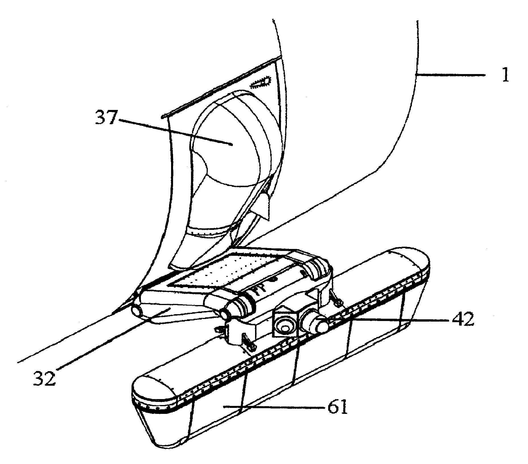
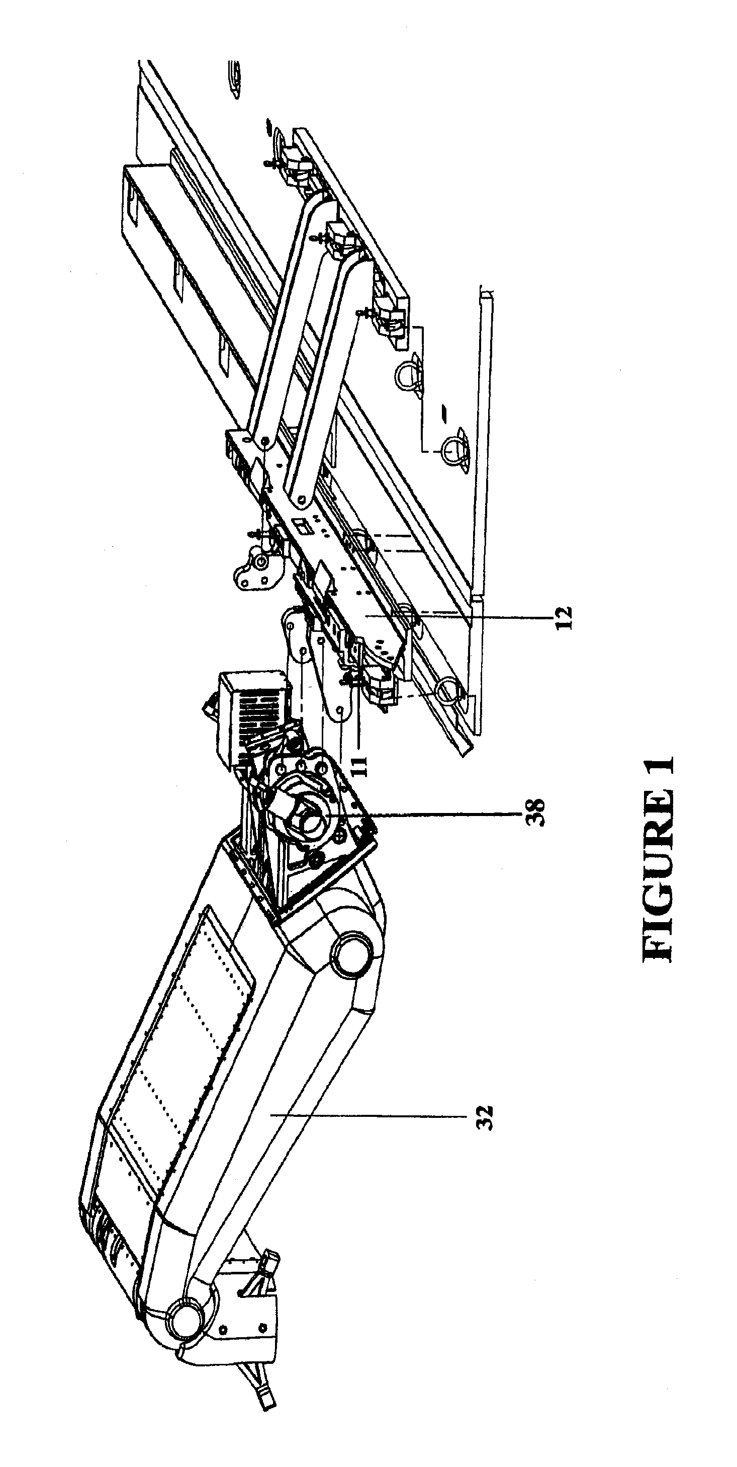
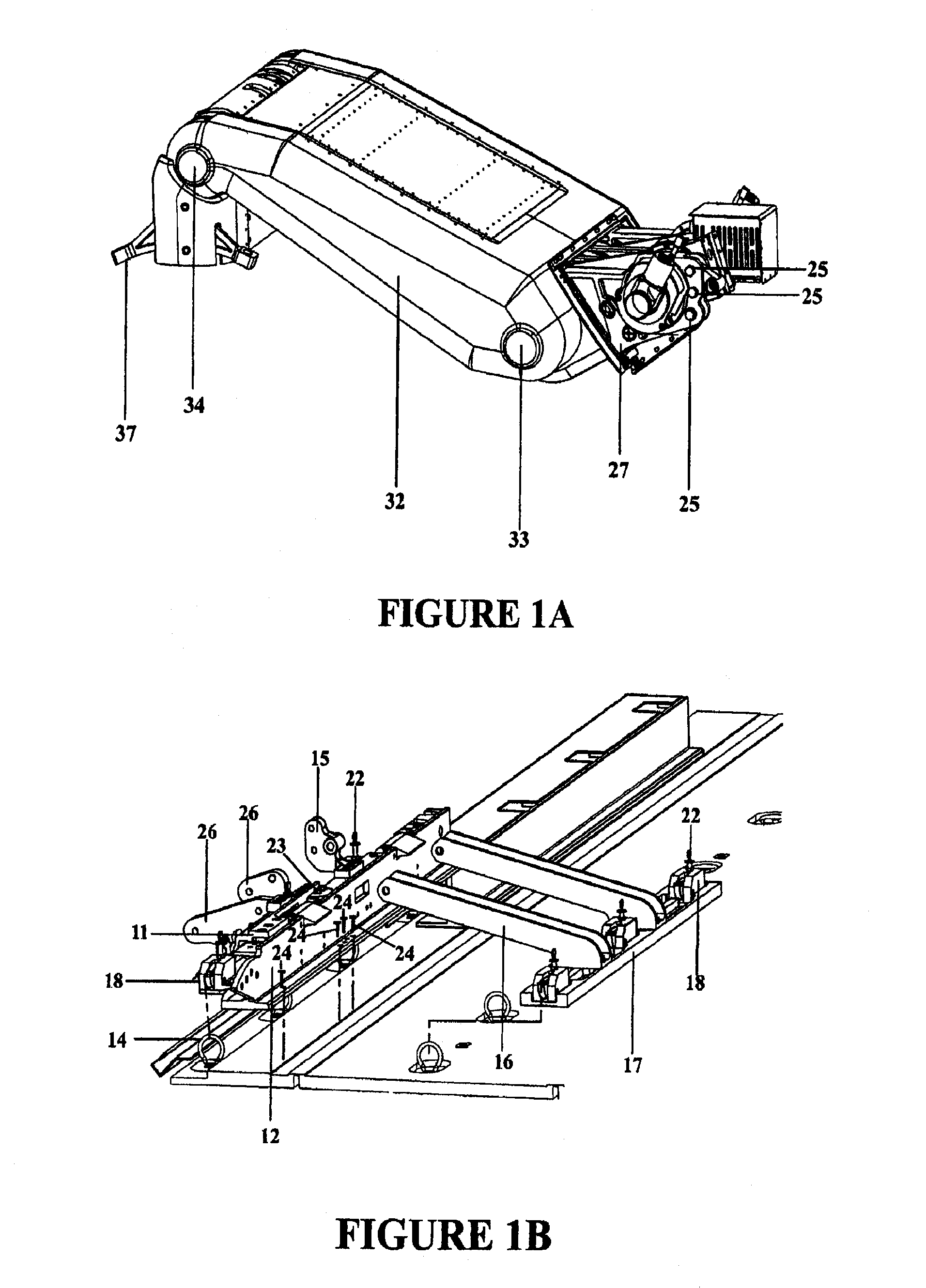
[0028]FIGS. 1 through 1B depicts an exploded overview of the primary structural and mechanical attachment mechanisms of a strut of the present invention assembled as it would normally be connected together and installed to achieve fitment of a pod or other apparatus aboard a Lockheed-Martin C-130 aircraft 1, including one or more adaptive mounting plates (AMP) 11. Adaptive mounting plates 11 can be perforated with bolt holes which interface and otherwise permit connectivity to a standard ADS rail 12, by means of multiple AMP restraint bolts 23 (as shown in FIG. 1B). Once the adaptive mounting plates 11 have been secured to the ADS rail 12, or a section of the ADS rail 12, the rail or section can be positioned and secured to the aircraft floor utilizing multiple ADS ...


PUM


Abstract

The system and apparatus of the present invention is generally comprised of a non-dedicated, temporarily installed, airborne special mission payload mounting system which is mechanically interfaced to the Air Deployment System (ADS) rails of a host cargo aircraft. Where a host aircraft does not possess ADS rails, an Adaptive ADS rail section typical of those used by the host aircraft, is installed to the existing cargo floor “D” rings using adjustable cam locks familiar to those skilled in the art of aircraft cargo restraint systems. Where the host aircraft does not have the required cargo “D” rings installed they are then temporarily installed within the “D” ring bolt sockets to enable the aircraft to accommodate mounting of the Adaptive ADS rail section plate. Once the ADS rail section and plate are installed, an Adaptive Mounting Plate (AMP) is placed over the ADS rail section and restrained in position by using multiple bolts, and the cargo “D” rings integral to the ADS rail securing the AMP in position using adjustable cam locks hooked through the ADS rail “D” rings thereby precluding the requirement for a load transfer (torque) pallet, or dedicated airframe modifications. Once the AMP is secured, an articulated or fixed position strut can be attached to it through the opened side doorway without removing the original door. Once the fixed position or articulated strut is bolted to the AMP, a one piece or segmented two piece pressurized door plug indented along its lower periphery to accommodate the protruding form factor of the fixed position or articulated strut is installed within the vacant doorway above the strut providing an airtight seal and thereby permitting pressurization of the aircraft. In-flight dynamic loads exerted upon the various mission payload pods are transferred through the strut to the interior ADS rail by the AMP and to various cargo “D” rings located on the aircraft floor by a plurality of removable Load Transfer Braces (LTB) hinged to the inboard side of the AMP which in turn transfers said dynamic loads to a Floor Loads Plate (FLP) secured to multiple cargo tie down “D” rings on the floor of the host aircraft by means of adjustable cam locks. Said removable load transfer braces being able to rapidly disconnect from the adjustable cam locks, “D” rings, and FLP for stowage in the vertical position, outboard of the cargo transit envelop as to permit in flight air drop operations. In flight, the articulated strut assembly can be extended below the fuselage to achieve a 360 degree unobstructed field of view (FOV) for a given payload, or retracted into the fuselage to change sensor payloads or re-load jettisonable stores. The preferred embodiment of the present invention can be installed or removed in minutes, does not interfere with crew egress, the aircraft flight performance envelope, or emergency procedures of the host aircraft while installed and further possesses redundant primary drive retraction systems along with a manual retraction system, and payload jettisoning system to preclude any danger in landing the aircraft should there be a problem retracting the various mission payloads.

Description

PRIORITY[0001]This application claims priority to Provisional Application No. 60 / 999,316 filed on Oct. 17, 2007, the entirety of which is hereby incorporated by reference.FIELD OF THE INVENTION[0002]This invention relates to a temporarily mounted, portable, modular, aircraft-based special mission mounting system which does not require airframe modifications to accommodate the external carriage of unique airborne hardware suites including command, control, communications, computer, intelligence, surveillance, reconnaissance, (C4ISR) sensing, detection, targeting, tracking, communications relay, unmanned vehicle telemetry, aircraft self defense pods, or jettisonable stores.BACKGROUND OF THE INVENTION[0003]Aircraft-based platforms are ideally suited for time sensitive emergency, as well as routine, sensing or other electronic based search, monitoring, surveillance and response activities. For example, numerous civilian and military based aircraft response agencies require high resoluti...

Claims


Application Information

Patent Timeline
IPC IPC(8): B64C1/20
CPCB64C1/1461B64D47/08B64D7/00B64C1/36
Inventor WOODLAND, RICHARDNEYEDLY, ROSS JAMES
Owner 1281329 ALBERTA
Why Eureka
Try Eureka