Concentrate burner

a burner and concentration technology, applied in the direction of lighting and heating apparatus, blast furnace components, blast furnaces, etc., can solve the problems of affecting the middle part of the shaft, no way of adjusting the amount of turbulence, etc., to facilitate the removal of agglomerations, improve the stability of the flame, and optimal swirl angle for the reaction gas

Inactive Publication Date: 2010-08-19
OUTOTEC OYJ
View PDF5 Cites 18 Cited by
  • Summary
  • Abstract
  • Description
  • Claims
  • Application Information

AI Technical Summary

Benefits of technology

[0019]In an application of the concentrate burner, there is an area free of guide vanes in the lower part at the lower end adjacent to the discharge orifice. This can facilitate the removal of agglomerations from the vicinity of the guide vanes and, still, it is possible to provide an optimal swirl angle for the reaction gas, determined by the guide vanes. It should be noted that the guide vanes could also be placed closer to the inlet channel, depending on the conditions of the applications.
[0020]In an application of the concentrate burner, the annular discharge orifice of the reaction gas chamber, in the lateral direction and outwards, is limited by a wall part that has the shape of a truncated cone, converging down and inward at an angle θ to the vertical axis. Such an inward inclination of the outer wall of the annular discharge orifice is advantageous, as it can further be used to improve the stability of the flame, increase the processing time of the concentrate mixture particles, improve the mixing and the chemical reaction, and to provide a preferable shape of flame. In most known burner structures, the frusto-conical wall part mentioned above expands down and outwards at an angle to the vertical axis, causing a positive radial velocity in the turbulent flow discharging from the discharge orifice, which in turn can result in a poor mixing of the reaction gas and the concentrate mixture particles, and could thus result in flow conditions disadvantageous to the chemical reaction and the combustion. The positive radial velocity increases with the amount of turbulen

Problems solved by technology

One problem with the known concentrate burner is that there is no way of adjusting the amount of turbulence.
The t

Method used


Image

  • Concentrate burner
  • Concentrate burner
  • Concentrate burner

Examples


Embodiment Construction

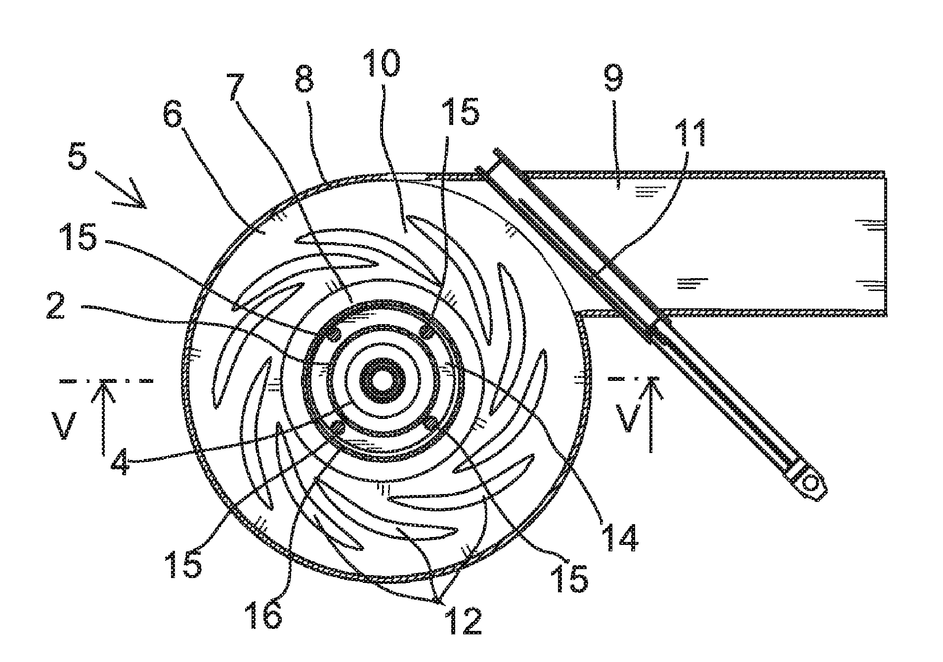
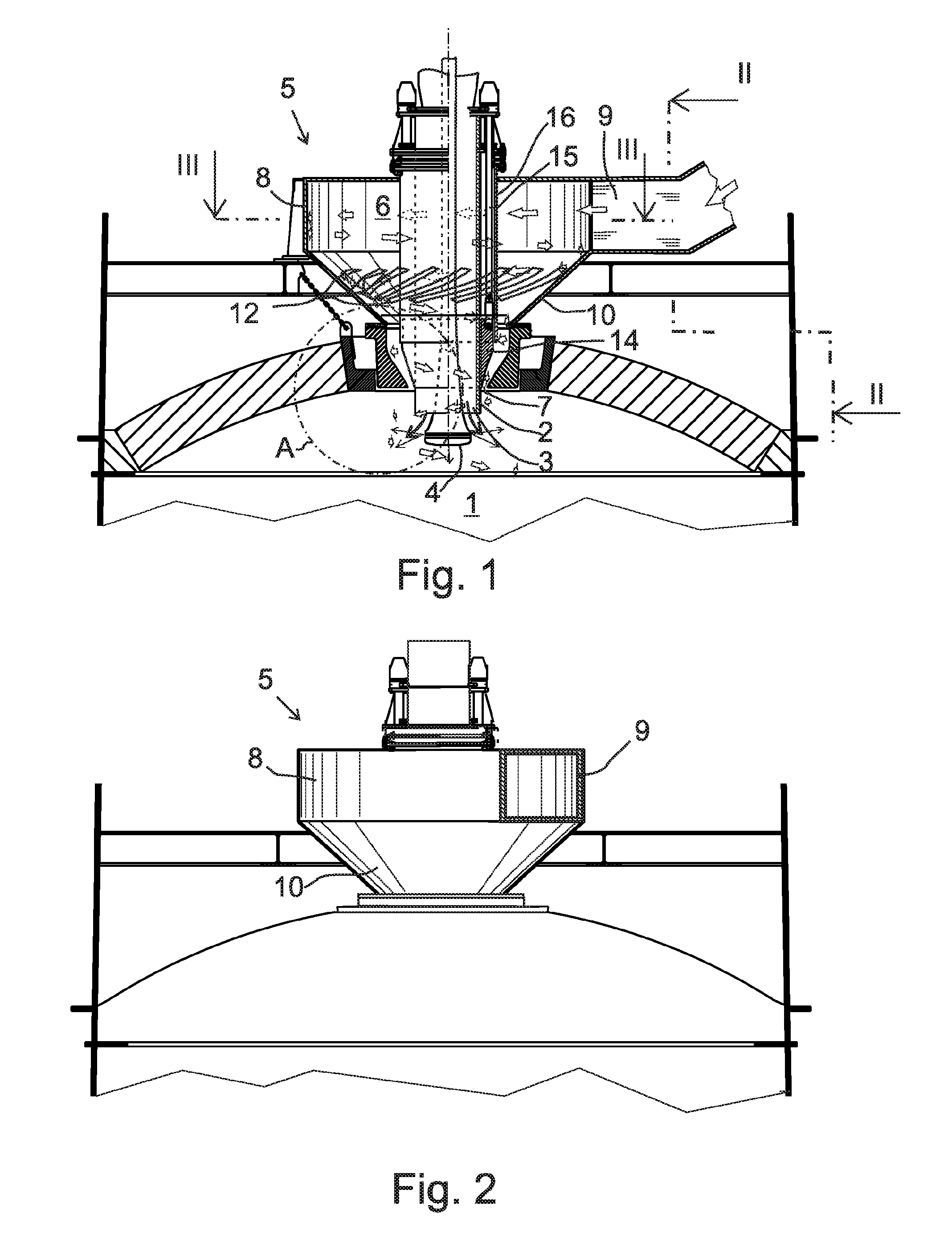
[0028]FIG. 1 shows a concentrate burner that is installed in the upper part of the reaction shaft 1 of a flash smelting furnace to feed pulverous concentrate mixture and reaction gas to the reaction shaft 1 of the flash smelting furnace.

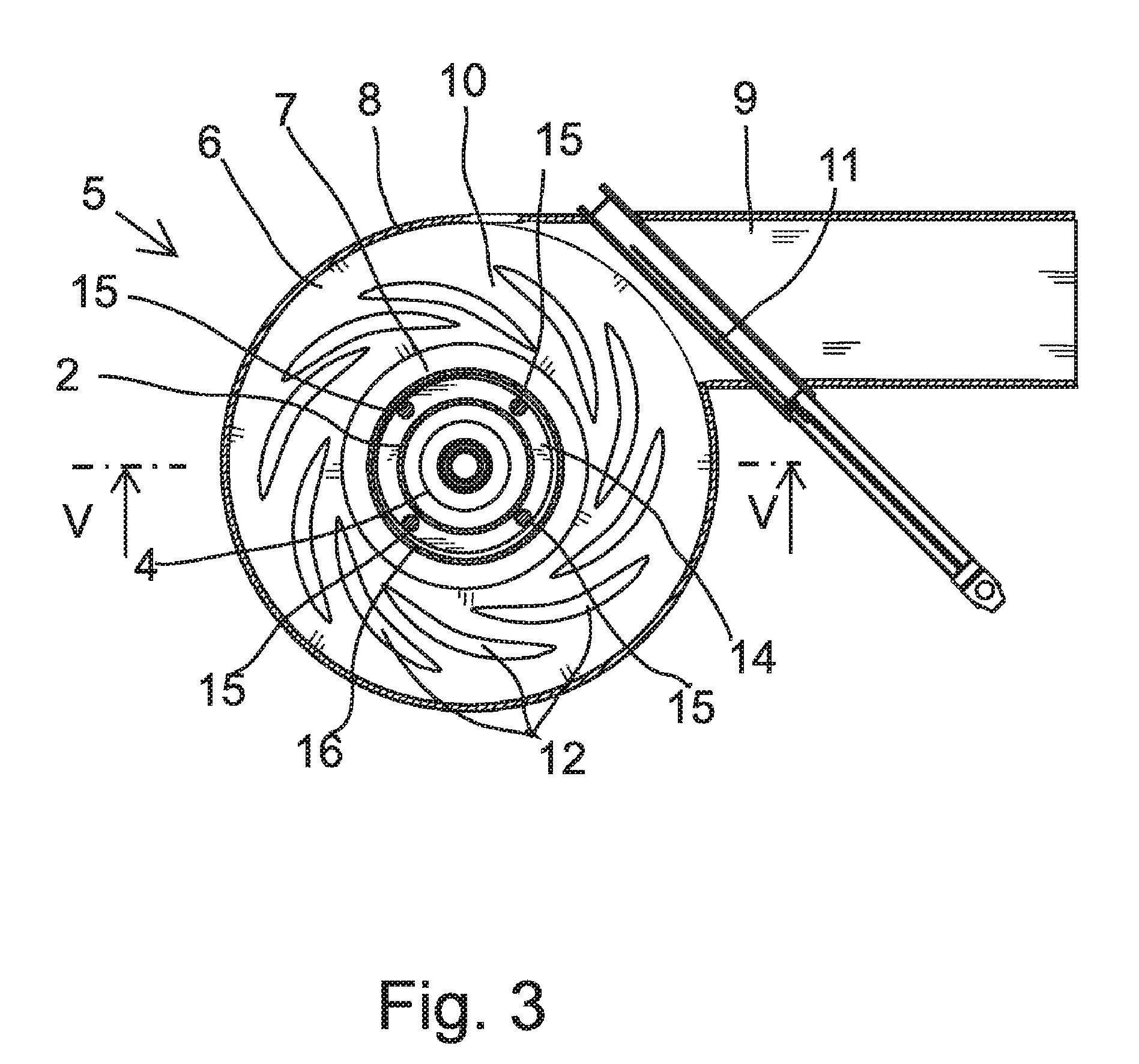
[0029]The concentrate burner includes a feeder pipe 2, its orifice 3 opening to the reaction shaft for feeding the concentrate mixture into the reaction shaft 1. Inside the feeder pipe 2, there is a dispersing device 4 that is placed concentrically, extending to a distance from the orifice 3 towards the inside of the reaction shaft 1. The dispersing device 4 directs the gas that is fed through it from the lower edge of the device to the side towards the flow of solid matter that is directed downwards outside the dispersing device. Furthermore, the concentrate burner includes a gas supply device 5 for feeding the reaction gas into the reaction shaft 1. The gas supply device includes a reaction gas chamber 6, which is located outside the reaction shaft...


PUM

PropertyMeasurementUnit
Angleaaaaaaaaaa
Angleaaaaaaaaaa
Angleaaaaaaaaaa

Abstract

A concentrate burner for feeding a pulverous concentrate mixture and reaction gas into the reaction shaft (1) of a flash smelting furnace. The concentrate burner includes a feeder pipe (2) for feeding the concentrate mixture into the reaction shaft (1), the orifice (3) of the feeder pipe opening to the reaction shaft, a dispersing device (4), which is arranged concentrically inside the feeder pipe (2) and which extends to a distance from the orifice inside the reaction shaft (1) for directing dispersing gas to the concentrate mixture flowing around the dispersing device. For feeding the reaction gas into the reaction shaft (1), a gas supply device (5) includes a reaction gas chamber (6), which is located outside the reaction shaft and opens to the reaction shaft (1) through an annular discharge orifice (7) that surrounds the feeder pipe (2) concentrically for mixing the reaction gas discharging from the discharge orifice with the concentrate mixture discharging from the middle of the feeder pipe, the concentrate mixture being directed to the side by means of the dispersing gas. The reaction gas chamber (6) comprises a turbulent flow chamber, to which an inlet channel (9) opens tangentially for directing the reaction gas to the reaction gas chamber in a tangential direction. In the inlet channel (9), an adjusting member (11) is arranged for adjusting the cross-sectional area of the reaction gas flow.

Description

FIELD OF THE INVENTION[0001]The invention relates to a concentrate burner defined in the preamble of claim 1.BACKGROUND OF THE INVENTION[0002]A flash smelting process takes place in a flash smelting furnace that consists of three sections: a reaction shaft, a lower furnace, and an uptake. In the flash smelting process, a pulverous concentrate mixture that consists of sulphidic concentrates, fluxes, and other pulverous components, is mixed with a reaction gas by means of the concentrate burner in the upper part of the reaction shaft. The structure of the concentrate burner plays a radical role in the proper functioning of the flash smelting process. The reaction gas can comprise air, oxygen-enriched air or oxygen. The concentrate burner comprises a number of concentric channels, through which the reaction gas and the concentrate are blown to and mixed in the furnace. Concentrate burners are known previously, for example, from publications FI 98071 B and FI 100889 B. This burner, know...

Claims


Application Information

Patent Timeline
IPC IPC(8): C22B1/00F27D3/16F27D3/18C21B7/00
CPCC22B15/0047F27D3/18F27D3/16C22B15/00
Inventor SIPILA, JUSSIPELTONIEMI, KAARLEBJORKLUND, PETERXIA, JILIANG
Owner OUTOTEC OYJ
Why Eureka
Try Eureka