Multibeam Active Discrete Lens Antenna

a discrete lens and active technology, applied in the field of multibeam antennas, can solve the problems of difficult manufacturing, heavy weight of conventional dielectric lenses, and difficult manufacturing, and achieve the effects of reducing volume, mass, cost and complexity, and improving radiative performan

Active Publication Date: 2010-08-19
EUROPEAN SPACE AGENCY
View PDF3 Cites 31 Cited by
  • Summary
  • Abstract
  • Description
  • Claims
  • Application Information

AI Technical Summary

Benefits of technology

[0013]The invention aims at providing an improved architecture for a discrete active lens multib

Problems solved by technology

This type of architecture presents severe problems of accommodation when used onboard satellites.
However they are very expensive, due to the high number of radiating feeds constituting the array and to the need for a complex beam-forming network.
Conventional dielectric lenses are too heavy and lossy for large aperture antennas, and they require at least one curved surface, which make them difficult to manufacture.
A drawback of passive lens antennas of this kind is associated to the significant losses introduced: indeed, a large part of the power impinging on the back array (for a tr

Method used


Image

  • Multibeam Active Discrete Lens Antenna
  • Multibeam Active Discrete Lens Antenna
  • Multibeam Active Discrete Lens Antenna

Examples


Embodiment Construction

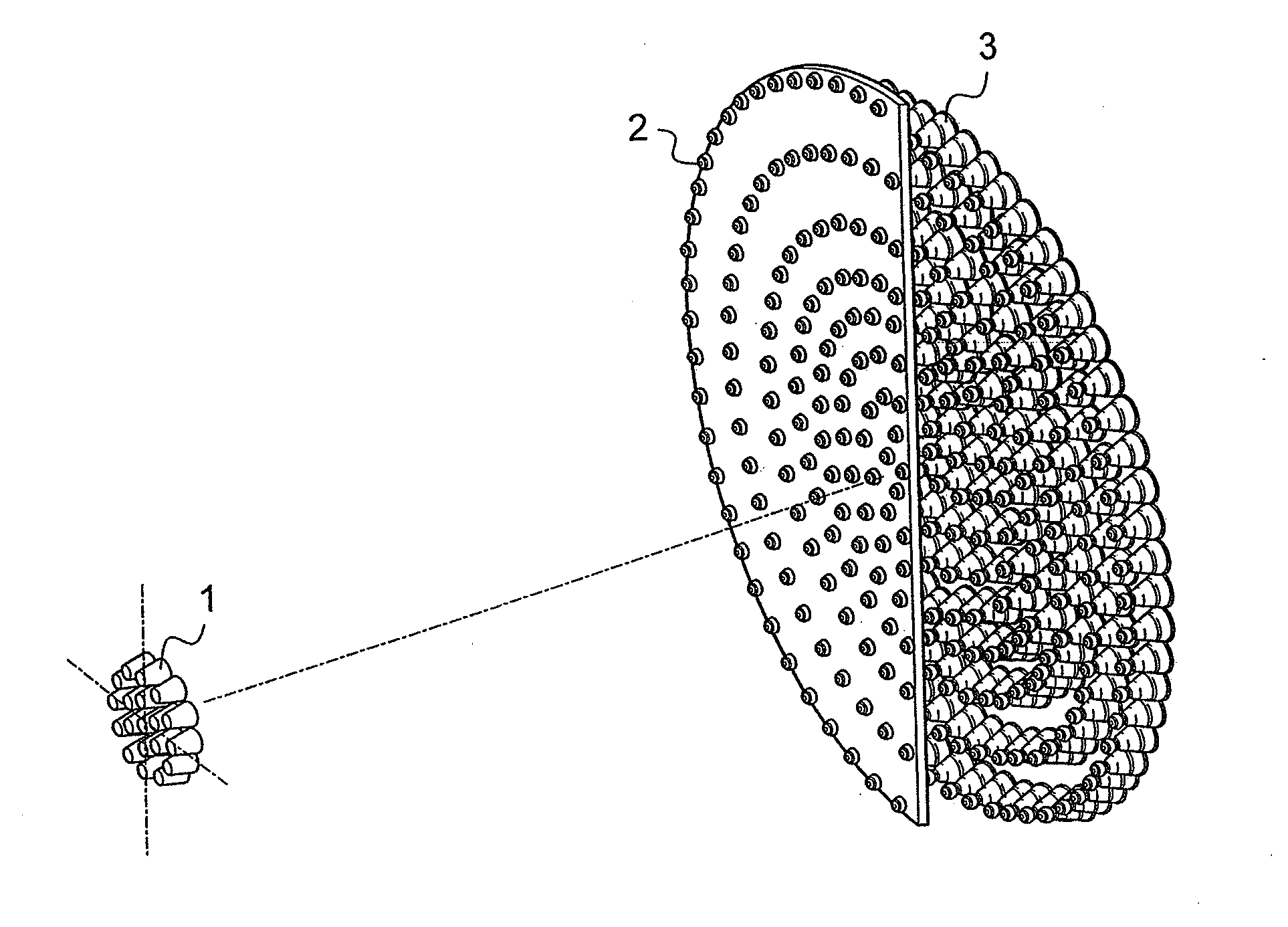
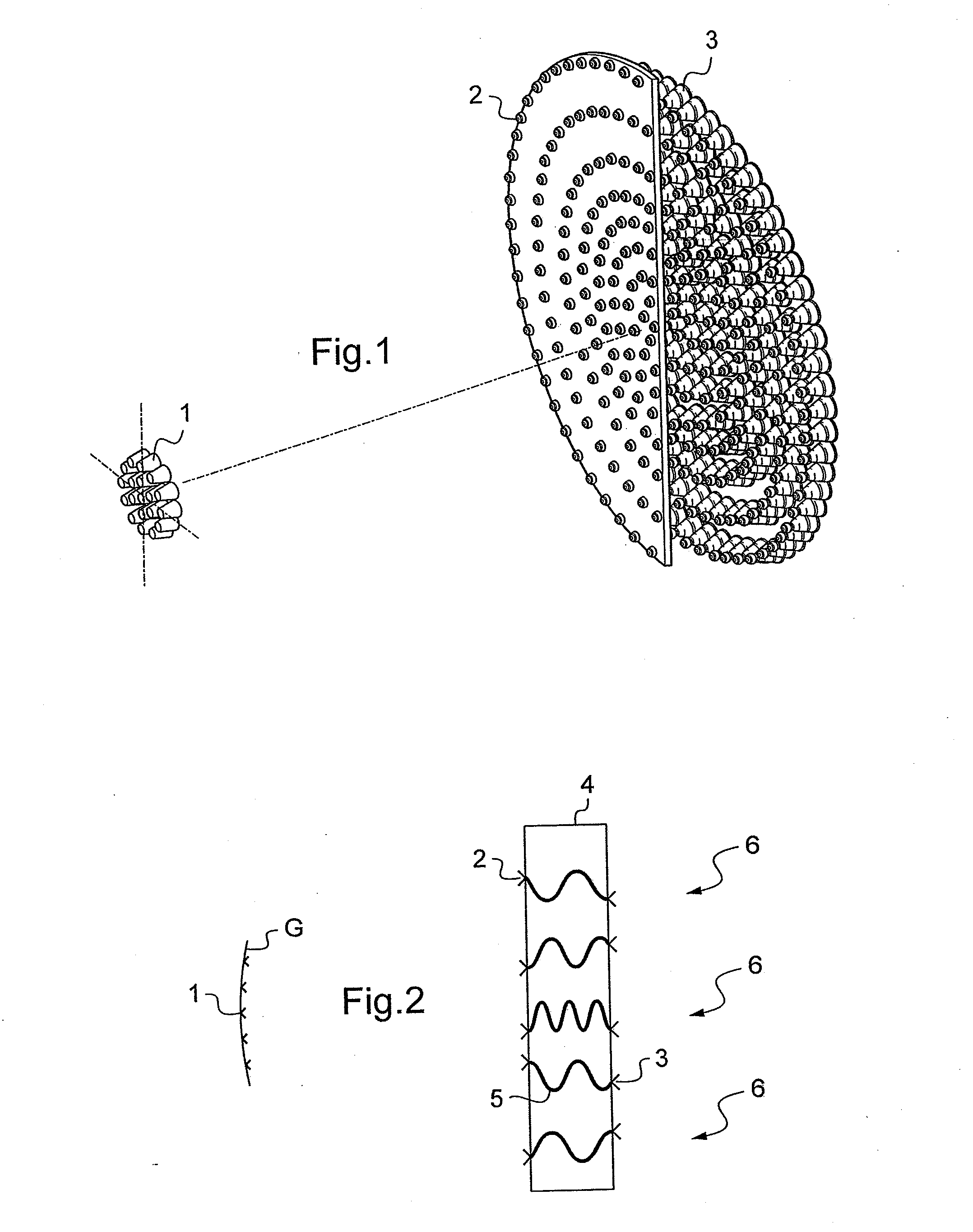
[0041]For a better understanding of the present invention and the advantageous results obtained with respect to prior art, an exemplary block diagram of a generic passive discrete lens, working in reception, is shown on FIG. 1. While the radiating elements 3 of the front array form the radiative side of the lens, the elements 2 of the back array interact with the primary feeds 1 located in the focal zone of the lens. Each radiating element of the front array is interconnected to an homologue element of the back array through transmission lines 5 of different lengths such that an impinging plane wave 6 is focused in a point of the focal surface G of the lens where a primary feed capable of collecting the impinging plane wave energy is located.

[0042]Let ρ be the radial coordinate of a radiating element of the back array (ρ=0 at the center of the array), r the radial coordinate of the corresponding element of the front array and F the focal length of the lens. Then, as shown in the abo...


PUM

PropertyMeasurementUnit
Efficiencyaaaaaaaaaa
Poweraaaaaaaaaa
Diameteraaaaaaaaaa

Abstract

A multibeam antenna comprising: a plurality of primary radiating elements, each associated to a respective beam; and an active radiating structure comprising a first planar array of radiating elements, a second planar array composed by a same number of radiating elements, a set of connections between each radiating element of the first planar array and one corresponding element of the second planar array, and a set of power amplifiers for amplifying signals transmitted through said connections; wherein: the relative positions of the radiating elements of the first and second planar arrays and phase delays introduced by said connections are such that the radiating structure forms an active discrete converging lens; and said primary radiating elements are clustered on a focal surface of said lens, facing the first planar array; characterized in that said first and second planar arrays are both aperiodic. A method of manufacturing such an antenna.

Description

BACKGROUND OF THE INVENTION[0001]The invention relates to a multibeam antenna, and in particular to a transmit and / or receive multibeam antenna for satellite applications, designed to operate in the microwave part of the spectrum (300 MHz-300 GHz).[0002]It is well known in the art of antenna engineering that the generation of directive beams implies using antennas with large electric dimensions, usually based on reflectors.[0003]A conventional solution for generating a coverage characterized by contiguous high directivity spot beams consists in using several reflector antennas—typically three or four in reflection and the same number in transmission—in order to generate interleaved beams. See S. K. Rao “Parametric Design and Analysis of Multiple-Beam Reflector Antennas for Satellite Communications”, IEEE Antennas and Propagation Magazine, Vol. 45, No. 4, August 2003. This type of architecture presents severe problems of accommodation when used onboard satellites.[0004]Phased arrays ...

Claims


Application Information

Patent Timeline
IPC IPC(8): H01Q19/06H01P11/00
CPCH01Q3/46H01Q15/02Y10T29/49016H01Q21/0018H01Q25/008H01Q15/06
Inventor TOSO, GIOVANNIANGELETTI, PIERORUGGERINI, GIANFRANCOBELLAVEGLIA, GIANCARLO
Owner EUROPEAN SPACE AGENCY
Why Eureka
Try Eureka