
Fully reflective and highly thermoconductive electronic module and method of manufacturing the same

a technology of electronic modules and thermoconductive materials, applied in the direction of dielectric characteristics, semiconductor/solid-state device details, printed circuit non-printed electric components association, etc., can solve the problems of led not being able to survive at an elevated temperature, generating a lot of heat, and rapidly deteriorating luminance of led

Active Publication Date: 2010-08-26
NAT TAIWAN UNIV
View PDF22 Cites 38 Cited by
  • Summary
  • Abstract
  • Description
  • Claims
  • Application Information

AI Technical Summary

Benefits of technology

[0016]It is therefore an objective of the present invention to provide a fully reflective and highly thermoconductive electronic module and a method of manufacturing the same, wherein the optical, electrical and thermal requirements may be addressed simultaneously.
[0018]The present invention further provides a method of manufacturing a fully reflective and highly thermoconductive electronic module. The method includes the steps of: grinding and oxidizing a metal bottom layer to make the metal bottom layer have a lower reflective surface; providing a patterned metal wiring layer; interposing a transparent ceramic layer between the metal wiring layer and the metal bottom layer to form an assembly; and placing the assembly in a high-temperature environment to make the transparent ceramic layer bond the metal bottom layer and the metal wiring layer together. Thus, it is possible to enhance the heat dissipating ability and the light reflection ability, and to provide the electrical connection.

Problems solved by technology

A typical power component, such as a solid relay, is similar to the CPU of the computer and generates a lot of heat.
However, the major barrier on the applications of the LED as the light source is that the LED cannot survive at an elevated temperature.
Generally speaking, the temperature of the LED cannot exceed 90° C. If the temperature of the LED is higher than 90° C., the luminance thereof rapidly deteriorates.
So, the rapid heat dissipating ability of the heat dissipation substrate in contact with the LED has become a greatest challenge for determining whether the LED can become the illumination light source or not.
One of the bottleneck in the LED illumination technology is the heat dissipating problem.
If the heat cannot be rapidly dissipated, the temperature of the LED chip becomes too high, the light emitting efficiency of the LED chip is lowered, and the lifetime of the LED chip is shortened.
At the moment, all the available heat dissipating substrates are not able to cope with the optical, electrical and thermal requirements simultaneously.
However, the cost of such technique is very high.

Method used


Image

  • Fully reflective and highly thermoconductive electronic module and method of manufacturing the same
  • Fully reflective and highly thermoconductive electronic module and method of manufacturing the same
  • Fully reflective and highly thermoconductive electronic module and method of manufacturing the same

Examples


Embodiment Construction

[0033]The present invention will be apparent from the following detailed description, which proceeds with reference to the accompanying drawings, wherein the same references relate to the same elements.

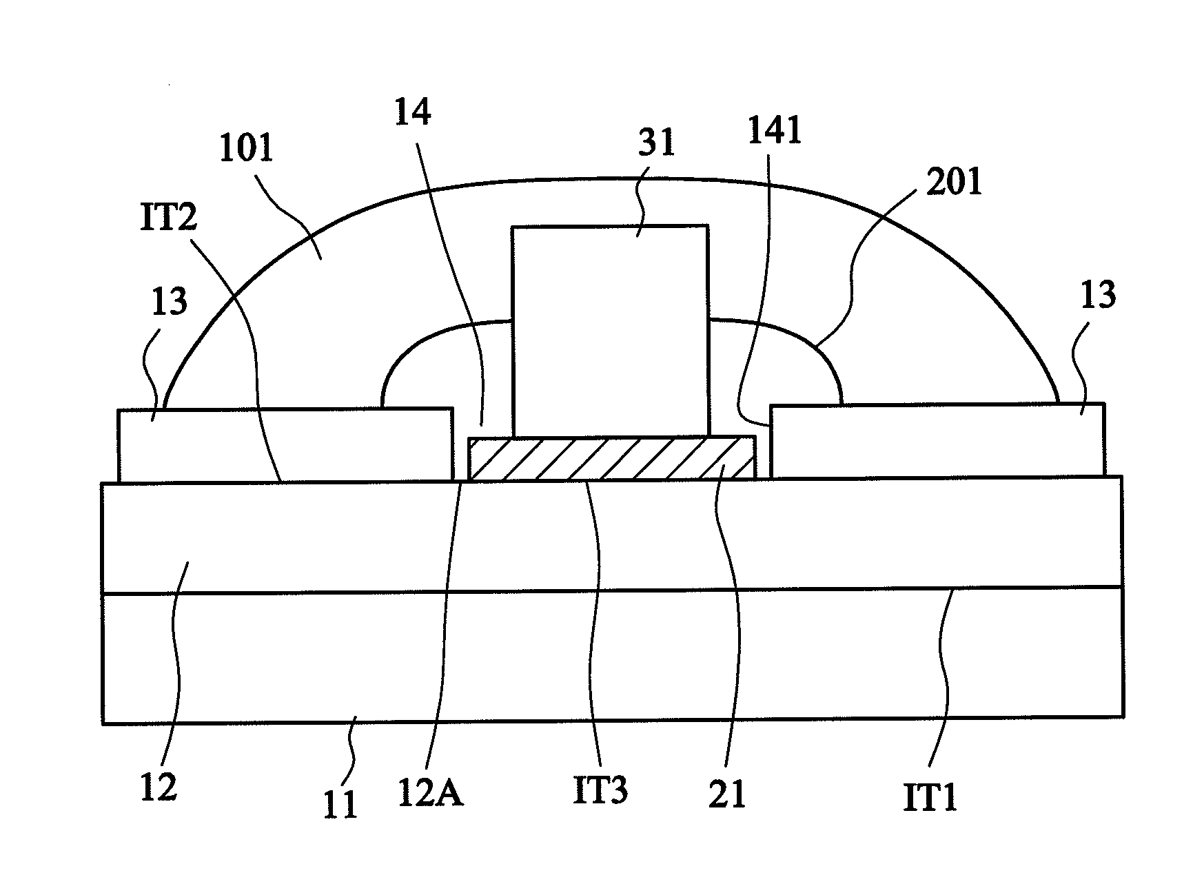
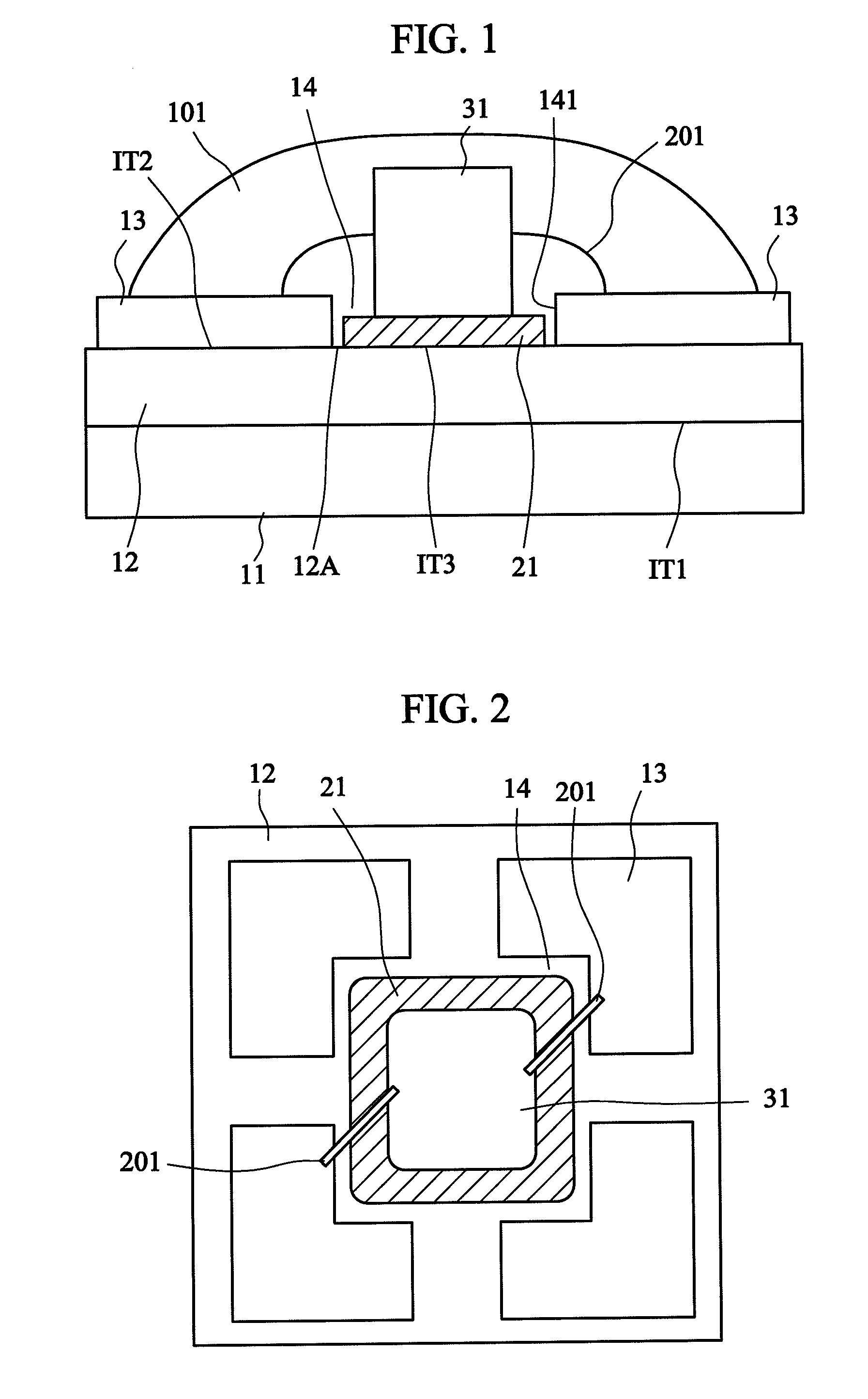
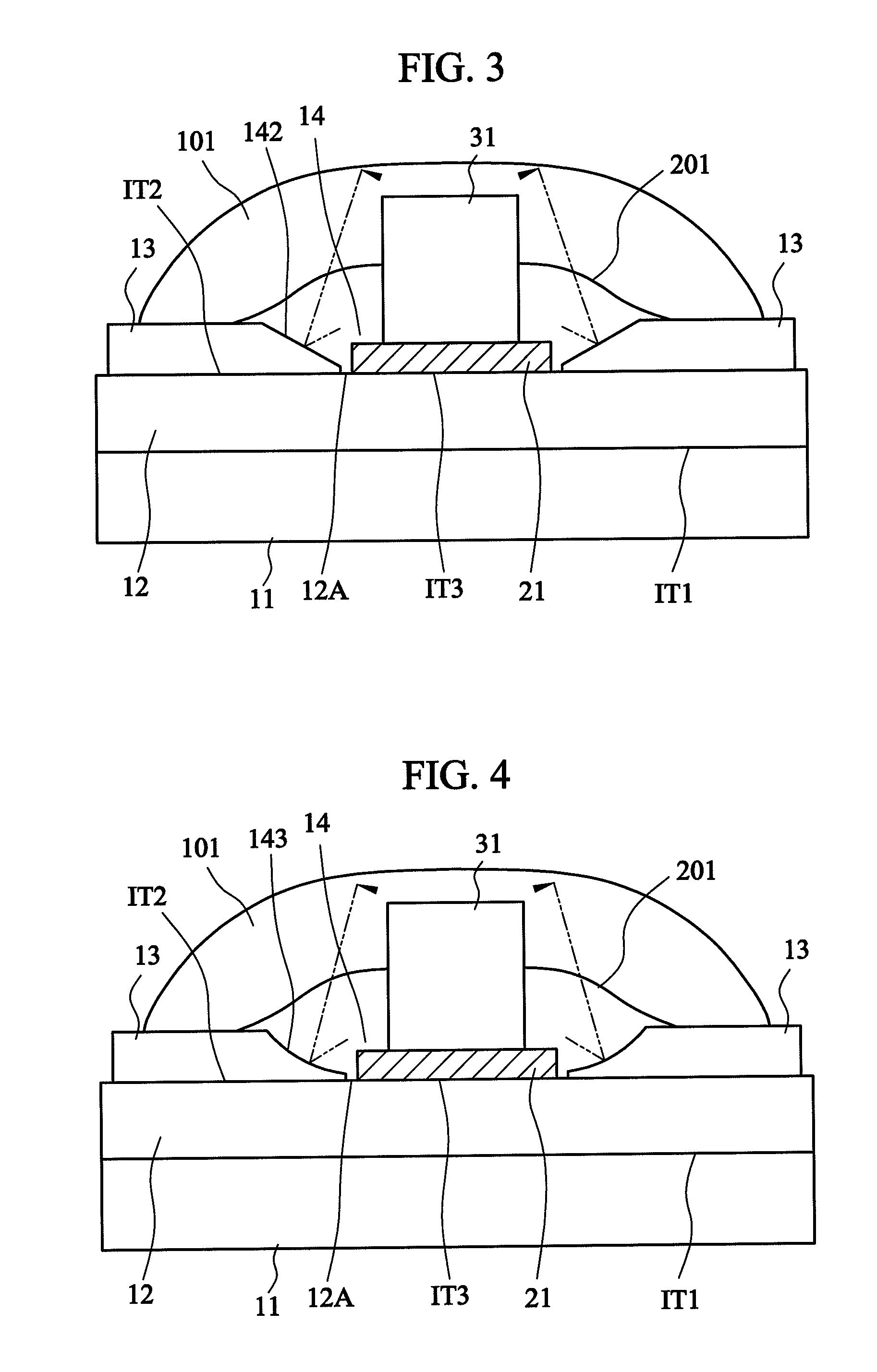
[0034]The invention provides an improved thin package assembly with a heat dissipating structure. FIG. 1 is a side view showing a package assembly according to a first embodiment of the invention. FIG. 2 is a top view showing the package assembly of FIG. 1. Referring to FIGS. 1 and 2, the package assembly of this embodiment includes a thermal conductive lower metal layer 11, an electric insulating ceramic layer 12, a patterned upper metal layer 13 and an electronic component 31.

[0035]The electric insulating ceramic layer 12 is disposed on and bonded to the thermal conductive lower metal layer 11. The patterned upper metal layer 13 is disposed on and bonded to the electric insulating ceramic layer 12. The patterned upper metal layer 13 is a single-layered metal layer and has an opening...


PUM

PropertyMeasurementUnit
Temperatureaaaaaaaaaa
Electrical conductoraaaaaaaaaa

Abstract

A fully reflective and highly thermoconductive electronic module includes a metal bottom layer, a transparent ceramic layer and a patterned metal wiring layer. The metal bottom layer has a lower reflective surface. The transparent ceramic layer has an upper surface and a lower surface. The lower surface of the transparent ceramic layer is bonded to the lower reflective surface of the metal bottom layer. The metal wiring layer is bonded to the upper surface of the transparent ceramic layer. The lower reflective surface reflects a first light ray, transmitting through the transparent ceramic layer, to the upper surface of the transparent ceramic layer. A method of manufacturing the fully reflective and highly thermoconductive electronic module is also disclosed.

Description

[0001]This application is a Continuation-in-Part of co-pending application Ser. No. 12 / 027,643, filed on Feb. 7, 2008, and for which priority is claimed under 35 U.S.C. §120; and this application claims priority of Application No. 099107276 filed in Taiwan, R.O.C. on Mar. 12, 2010 under 35 U.S.C. §119, the entire contents of all of which are hereby incorporated by reference.BACKGROUND OF THE INVENTION[0002]1. Field of the Invention[0003]The present invention relates to a fully reflective and highly thermoconductive electronic module and a method of manufacturing the same.[0004]2. Related Art[0005]Heat is generated when a light-emitting diode (LED) is operating with electrons flowing therethrough. The generation of heat increases the resistance and affects the flows of the electrons so that the function of the LED is significantly influenced. When the technology of manufacturing the LED is greatly enhanced, a line width in the LED is getting smaller and smaller, and the line density ...

Claims


Application Information

Patent Timeline
IPC IPC(8): H05K1/09H05K1/00B32B38/00
CPCH01L23/3735H01L24/49H01L33/64H01L2224/48091H01L2224/49107H01L2924/09701H05K1/0274H05K1/053H05K2201/0108H05K2201/10106H05K2201/2054H01L33/60H01L24/48H01L2924/00014H01L2224/73265H01L2924/12041H01L2924/181H01L2924/00H01L2924/00012H01L2224/45099H01L2224/45015H01L2924/207
Inventor TUAN, WEI-HSINGLEE, SHAO-KUAN
Owner NAT TAIWAN UNIV
Learn More