Adaptive Current Regulation for Solid State Lighting

a technology of current regulation and solid state lighting, applied in the direction of electric variable regulation, process and machine control, instruments, etc., can solve the problems of affecting the efficiency of lighting infrastructure replacement, inconvenient rewiring of lighting infrastructure, and many of the drivers of these power supplies are effectively incompatible with the existing lighting system infrastructure, etc., to achieve the effect of low cost components

Active Publication Date: 2010-08-26
CHEMTRON RES
View PDF40 Cites 300 Cited by
  • Summary
  • Abstract
  • Description
  • Claims
  • Application Information

AI Technical Summary

Benefits of technology

[0012]The exemplary embodiments of the present invention provide numerous advantages. The exemplary embodiments allow for solid state lighting, such as LEDs, to be utilized with the currently existing lighting infrastructure, including Edison sockets, and to be controlled by any of a variety of switches, such as phase modulating dimmer switches, which would otherwise cause significant operation problems for conventional switching power supp

Problems solved by technology

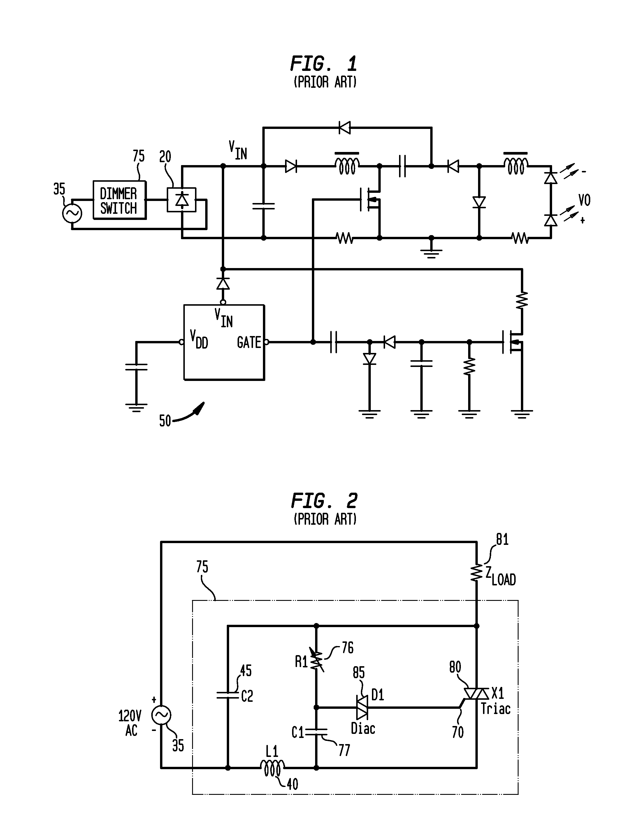
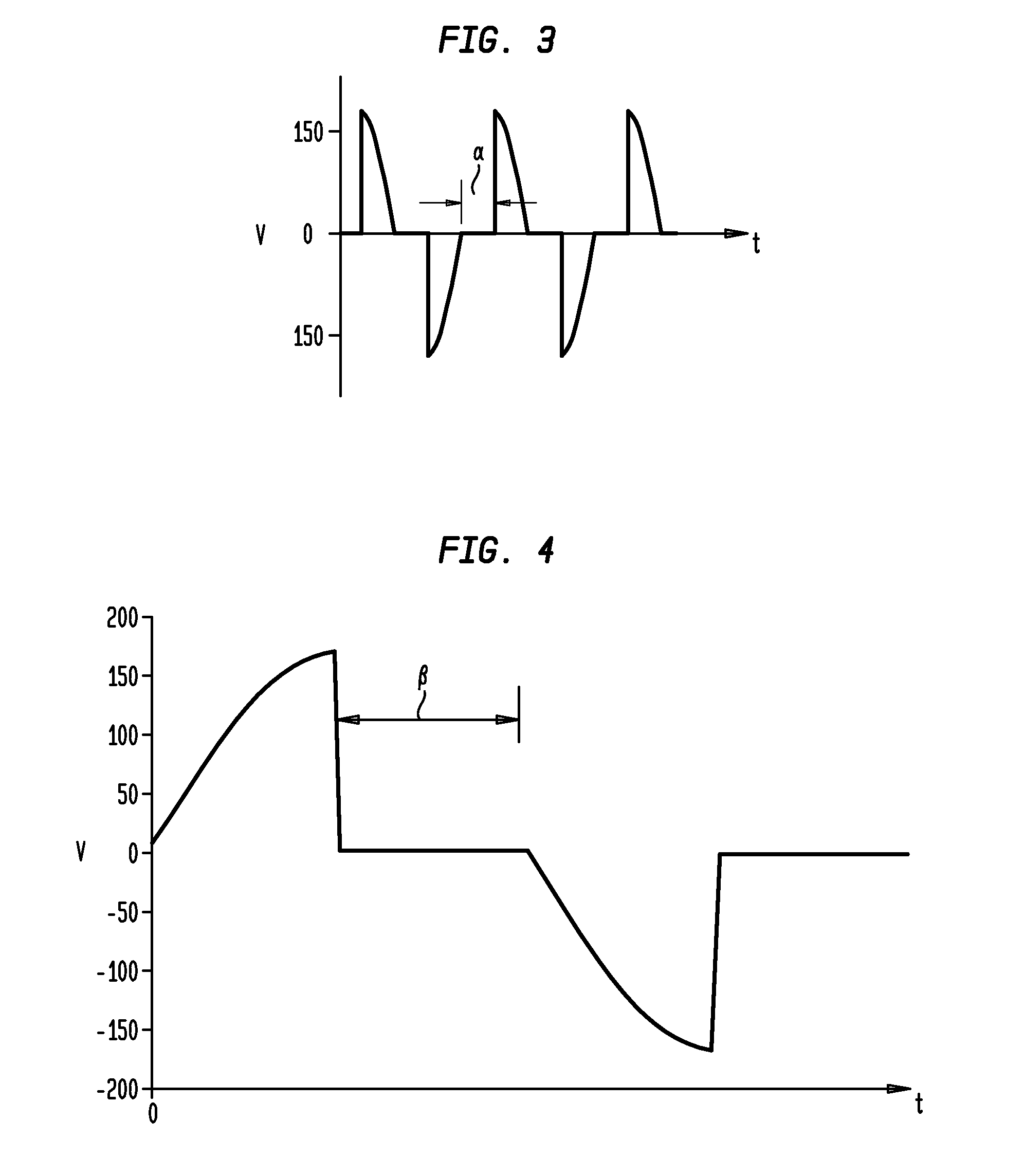
Many of these power supplies (i.e., drivers) are effectively incompatible with the existing lighting system infrastructure, such as the lighting systems typically utilized for incandescent or fluorescent lighting, such as infrastructure generally utilizing phase-modulating “dimmer” switches to alter the brightness or intensity of light output from incandescent bulbs.
Accordingly, replacement of incandescent lamps by LEDs is facing a challenge: either do a complete rewiring of the lighting infrastructure, which is expensive and unlikely to occur, or develop new LED drivers compatible with commercially available and already installed dimmers switches.
This proposal is complicated, requires excessively many components to implement, and is not particularly oriented to AC (alternating current) utility lighting.
When coupled with a dimmer, however, its LED regulation is poor and it does not completely support stable operation of the dimmer in the full range of output loads, specifically wh

Method used


Image

  • Adaptive Current Regulation for Solid State Lighting
  • Adaptive Current Regulation for Solid State Lighting
  • Adaptive Current Regulation for Solid State Lighting

Examples


Embodiment Construction

[0065]While the present invention is susceptible of embodiment in many different forms, there are shown in the drawings and will be described herein in detail specific exemplary embodiments thereof, with the understanding that the present disclosure is to be considered as an exemplification of the principles of the invention and is not intended to limit the invention to the specific embodiments illustrated. In this respect, before explaining at least one embodiment consistent with the present invention in detail, it is to be understood that the invention is not limited in its application to the details of construction and to the arrangements of components set forth above and below, illustrated in the drawings, or as described in the examples. Methods and apparatuses consistent with the present invention are capable of other embodiments and of being practiced and carried out in various ways. Also, it is to be understood that the phraseology and terminology employed herein, as well as...


PUM


Abstract

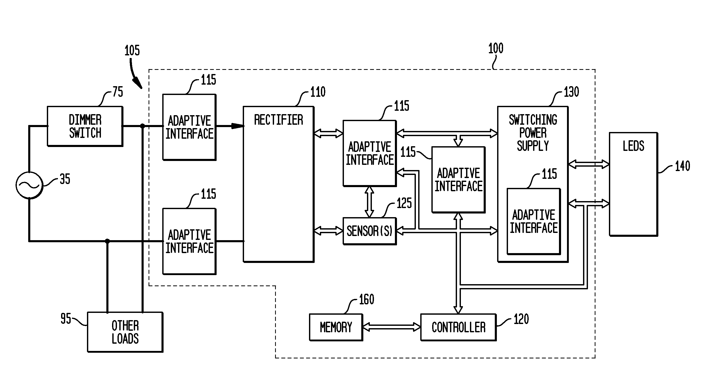
Exemplary embodiments provide an apparatus, system and method for power conversion to provide power to solid state lighting, and which may be coupled to a first switch, such as a dimmer switch. An exemplary system for power conversion comprises: a switching power supply comprising a second, power switch; solid state lighting coupled to the switching power supply; a voltage sensor; a current sensor; a memory; a first adaptive interface circuit to provide a resistive impedance to the first switch and conduct current from the first switch in a default mode; a second adaptive interface circuit to create a resonant process when the first switch turns on; and a controller to modulate the second adaptive interface circuit when the first switch turns on to provide a current path during the resonant process of the switching power supply.

Description

CROSS-REFERENCE TO RELATED APPLICATIONS[0001]This application is related to and is a continuation-in-part of U.S. patent application Ser. No. 11 / 655,558, filed Jan. 19, 2007, inventors Anatoly Shteynberg et al., entitled “Impedance Matching Circuit for Current Regulation of Solid State Lighting”, now U.S. Pat. No. ______ issued ______, which claims priority to and is a conversion of U.S. Provisional Patent Application Ser. No. 60 / 760,157, filed Jan. 20, 2006, inventors Anatoly Shteynberg et al., entitled “Off-Line LED Driver with Phase Modulation”, both of which are commonly assigned herewith, the contents of which are incorporated herein by reference with the same full force and effect as if set forth in their entireties herein, and with priority claimed for all commonly disclosed subject matter.FIELD OF THE INVENTION[0002]The present invention in general is related to power conversion, and more specifically, to a system, apparatus and method for supplying power to solid state ligh...

Claims


Application Information

Patent Timeline
IPC IPC(8): H05B37/02
CPCH05B33/0815H05B37/02Y02B20/347H05B33/0851H05B45/10H05B45/385H05B47/10Y02B20/30
Inventor SHTEYNBERG, ANATOLYRODRIGUEZ, HARRYLEHMAN, BRADLEY M.ZHOU, DONGSHENG
Owner CHEMTRON RES
Why Eureka
Try Eureka