High Peak and Average Power-Capable Microwave Window for Rectangular Waveguide

a rectangular waveguide and microwave window technology, applied in waveguide type devices, basic electric elements, electrical apparatuses, etc., can solve the problems of frequency dependence of the operation of the rectangular waveguide window, and none of the devices, however, disclose or teach the use of the rectangular waveguide microwave window for fundamental mode propagation, etc., to maximize the operating bandwidth optimize the transparency of the rectangular waveguide microwave window, and increase the average power capability of the waveguide window

Inactive Publication Date: 2010-08-26
VOSS SCI
View PDF10 Cites 14 Cited by
  • Summary
  • Abstract
  • Description
  • Claims
  • Application Information

AI Technical Summary

Benefits of technology

[0016]It is a further object of the presently claimed invention to teach the use of passive and active cooling of the window to increase the average power capability of the waveguide window.
[0017]A specific implementation of the newly disclosed high peak power-capable rectangular waveguide window utilizes multiple dielectric interfaces, each with a specific thickness and separated by specific distances. The region between the multiple interfaces can be filled with vacuum or a high pressure gas that inhibits electrical flashover (for instance, sulfur hexafluoride). The presently claimed invention teaches the use of a multitude of metallic septums (or septa). Each septum passes through one of the dielectric interfaces and is oriented in a way such that it is everywhere normal to the polarization of the incident electric field. When oriented in such a manner the incident microwav

Problems solved by technology

A limitation of the half-wave window described above is that its operation is frequency dependent, and operates over a narrow bandwidth (typically a fraction of the nominal empty waveguide bandwidth).
None of these devices, however, disclose or teach the use of a microwave wi

Method used


Image

  • High Peak and Average Power-Capable Microwave Window for Rectangular Waveguide
  • High Peak and Average Power-Capable Microwave Window for Rectangular Waveguide
  • High Peak and Average Power-Capable Microwave Window for Rectangular Waveguide

Examples


Embodiment Construction

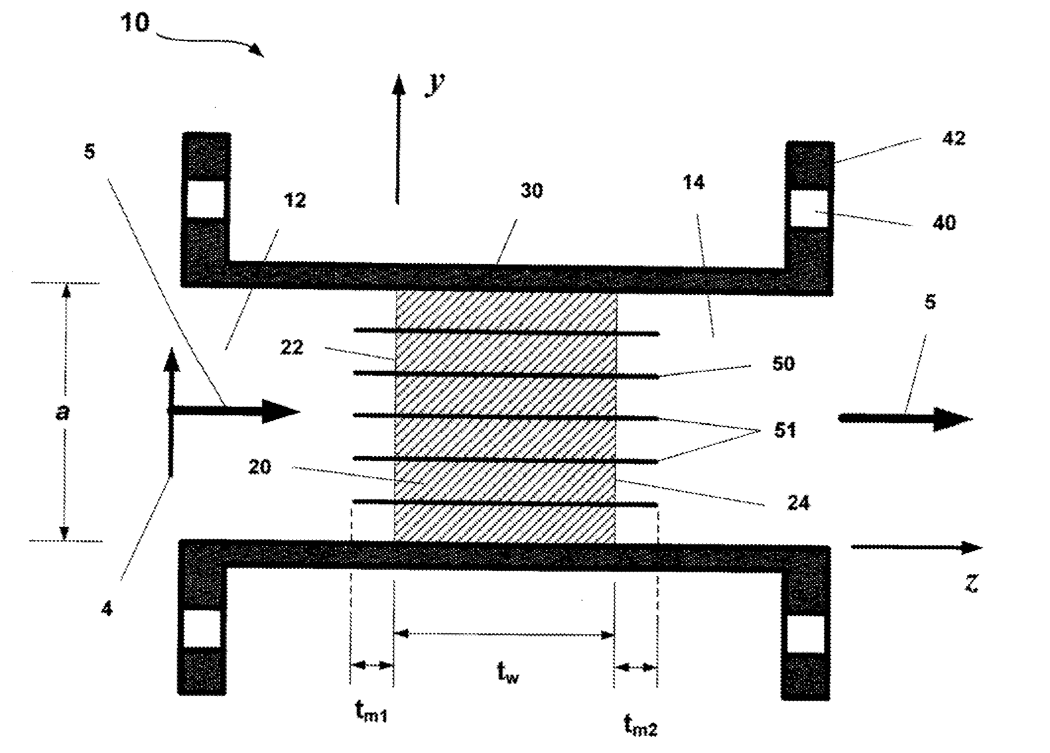
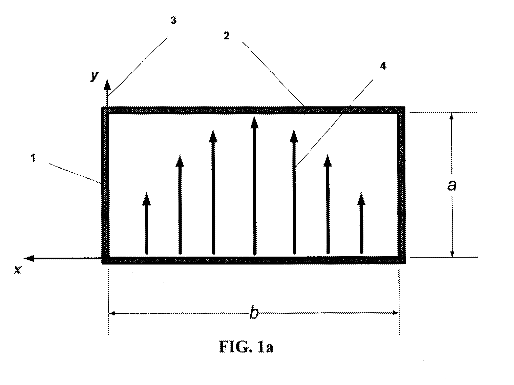
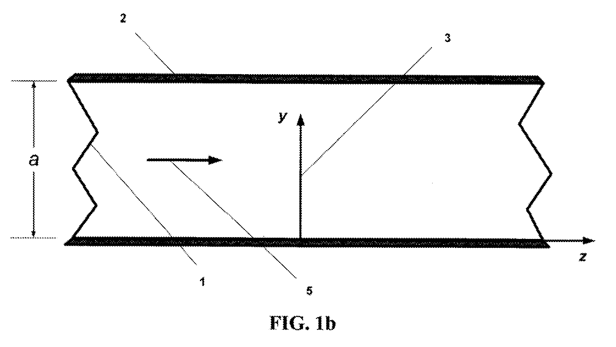
[0038]The geometry of rectangular waveguide is shown in the principal plane cross sections in FIGS. 1a, 1b and 1c. The narrowwall 1 has dimension a, while the broadwall 2 has dimension b, b>a, and for standard rectangular waveguide b˜2a. All boundaries of the waveguide are metal and are good electrical conductors. For the claimed invention the rectangular waveguide can be standard (one in which the dimension of the broadwall is approximately twice the dimension of the narrowwall) or non-standard (one in which the dimension of the broadwall is more than twice the dimension of the narrowwall). A standard right-hand coordinate system 3 is assigned to the geometry and is also shown in the figures. As indicated in FIG. 1b, an electromagnetic wave is assumed propagating 5 along the z-axis direction. The mode of the propagating electromagnetic wave is assumed to be that of the TE10 rectangular waveguide mode 4, as shown in FIG. 1a, also known as fundamental mode of the rectangular waveguid...


PUM


Abstract

A high peak and high average power-capable microwave/radio frequency window for use in rectangular or other waveguide transmission line geometries. The waveguide microwave window provides a physical barrier, or interface, between two regions on either side of the window. The window presents a relatively transparent interface for the microwave signal that is propagating in the waveguide. In an electrical sense the window will exhibit low return loss. The microwave window inhibits multipactor phenomena, suppresses electrical breakdown and transmits high peak power radio frequency signals. The microwave window also provides a mechanism for both passive and active cooling to allow operation at high average power. The applications for the claimed invention include use as part of: High Power Microwave (HPM) generators and systems; HPM sources and systems employed in and by particle accelerators; plasma processing systems; and numerous other applications that utilize high power microwave signals.

Description

CROSS-REFERENCE TO RELATED APPLICATIONS[0001]This application claims priority to Provisional Application Ser. No. 61 / 154,044, filed on Feb. 20, 2009 entitled “High Peak Power-Capable Microwave Window for Rectangular Waveguide”.BACKGROUND OF THE INVENTION[0002]1. Field of the Invention (Technical Field)[0003]The presently claimed invention relates to a method and apparatus associated with the field of microwave or radio frequency (RF) technology and generally related to microwave waveguides and devices for interconnecting waveguides. More particularly, the presently claimed invention relates to use in a standard rectangular waveguide (with a nominal 2:1 cross sectional aspect ratio) operating in fundamental mode, though the claimed invention is also applicable for use in other waveguide transmission line geometries. The presently claimed invention allows the transport of extremely high peak power, high average power, and intense electromagnetic fields from one waveguide region (with ...

Claims


Application Information

Patent Timeline
IPC IPC(8): H01P1/08
CPCH01P1/08
Inventor COURTNEY, CLIFTON C.VOSS, DONALD E.
Owner VOSS SCI
Why Eureka
Try Eureka