Apparatus for controlling aircraft ground movement

a technology for controlling aircraft and ground movement, applied in vehicle position/course/altitude control, process and machine control, instruments, etc., can solve the problems of tugs being often short taking time to attach to aircraft, and affecting the efficiency of tugs at airports, so as to reduce turnaround times, facilitate operation, and increase efficiency at airports

Inactive Publication Date: 2010-08-26
BOREALIS TECH LTD
View PDF7 Cites 15 Cited by
  • Summary
  • Abstract
  • Description
  • Claims
  • Application Information

AI Technical Summary

Benefits of technology

[0025]It would further be advantageous to have a means for controlling the movements of an aircraft on the ground. It would be further advantageous for this means to be remote from said aircraft and to be operable by airport ground staff.
[0028]It is a further object of the invention to provide said means which are intuitive, safe, and easy to operate.
[0029]It is a further object of the present invention to provide a method and apparatus for reversing an aircraft on the ground in order to decrease turnaround times and increase efficiency at airports.
[0030]An apparatus for controlling the movement of an aircraft having a self-propelled nosewheel, on the ground, is disclosed. The apparatus comprises a control arm; a control unit; means for transmitting information to said self-propelled nosewheel; means for receiving information at said self-propelled nosewheel; and means for controlling at least one of the speed and direction of said nosewheel; whereby airport ground staff can intuitively control the movements of said aircraft by holding said arm and moving it in the direction of required movement of said aircraft.

Problems solved by technology

Tugs are commonly in short supply at airports and delays are often caused while aircraft wait for tugs.
Additionally, the tug takes time to attach to the aircraft.
The use of reverse thrust to move the aircraft backwards is less common since it provides limited maneuverability, is noisy, and uses a large amount of fuel.
Specifically, the powerback causes the jet exhaust to blow debris up from the ground, which often is then sucked into the intake.
This is expensive to install at airports and may not be large enough for all aircraft that may require it in the future.
Space in this area is severely restricted.
The shape and volume of the bay into which the undercarriage wheel retracts is of fixed size and cannot easily be altered.
Further, using a bigger wheel and a bigger tire, in order to house a motor powerful enough to move the plane unassisted, will increase the mass of that part of the undercarriage, which may have deleterious effects on the balance and handling of the aircraft.
Thus, installation of any of these motors requires serious modification of aircraft and as such they have not been widely used.
Therefore, improved airport procedures and methods associated with such equipment have not been developed.
However, this magnetic field configuration induces substantial rotor currents in the rotor windings, and the currents produce induction based torque to rotate the rotor.

Method used


Image

  • Apparatus for controlling aircraft ground movement
  • Apparatus for controlling aircraft ground movement
  • Apparatus for controlling aircraft ground movement

Examples


first embodiment

[0040]In the invention, a method of reversing an aircraft on the ground comprises driving the aircraft using at least one self-propelled undercarriage wheel, said undercarriage wheel comprising an axle member, a wheel member, a drive member having a fixed element connected to said axle member and at least one driven element attached to said wheel member, for rotating said wheel member, and a tire affixed to said wheel member.

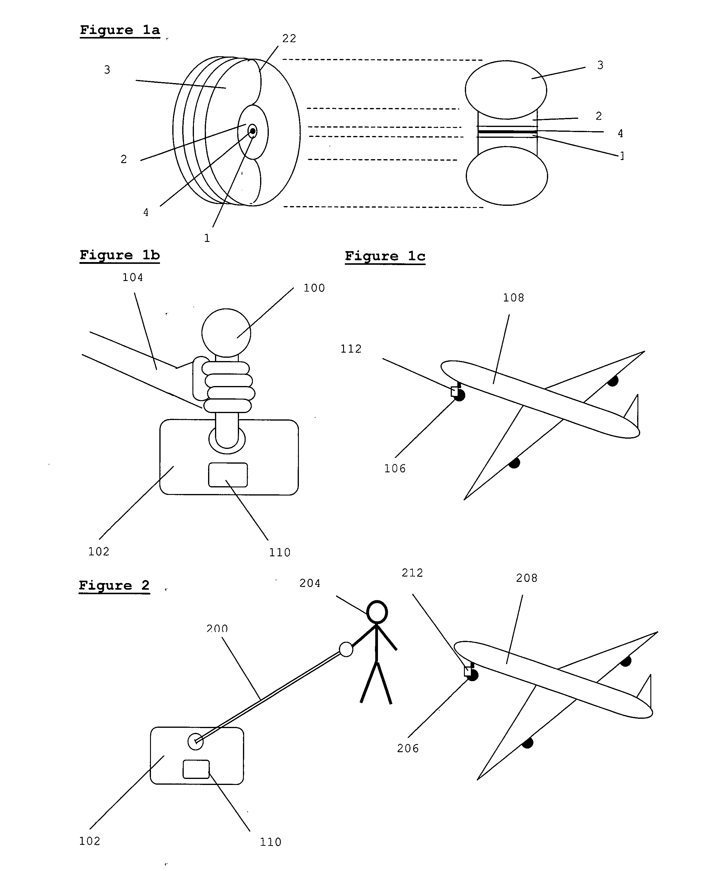
[0041]It will be readily appreciated that there are many possible configurations of an undercarriage wheel of the present invention. By way of example only, FIG. 1a shows in schematic form an undercarriage wheel having a fixed member 1 mounted on axle 4. Driven member 2 is rotatably mounted on fixed member 1. Tire 3 is externally connected to driven member 2. Tire 3 has bulge 22.

[0042]Preferably, said drive member is a high phase order electric induction motor. Said drive member may also be any other type of induction motor or other motor. Examples of suitable m...

second embodiment

[0102]In the invention, an apparatus for reversing an aircraft on the ground is disclosed, comprising at least one self-propelled undercarriage wheel comprising an axle member, a wheel member, a drive member having a fixed element connected to said axle member and at least one driven element attached to said wheel member, for rotating said wheel member, a tire affixed to said wheel member, and means for controlling at least one of speed and at least one direction of said aircraft.

third embodiment

[0103]In the invention, an apparatus for reversing an aircraft on the ground with increased stability is disclosed comprising a reversing self-limiting feature. Said apparatus is as described in any and all of the previous text of the description. Said self-limiting feature is the reversible drive means located in the nosewheel, used as a brake, and operates as follows. When an aircraft equipped with regular reversing and braking means, which is reversing on the ground, brakes, a rearward tipping torque is generated. The tipping risk is greatest when the braking wheels are located at the centre of the aircraft, especially when, as is usually the case, there are no tail wheels. (For this reason, pilots are trained not to brake during reversing on the ground.) Thus, locating the drive means and thus the braking means in the nosewheel increases stability to a degree. Braking may be accomplished using the drive means by driving the drive means in reverse, as described above, or by stopp...


PUM


Abstract

A method and apparatus is disclosed for reversing an aircraft on the ground comprising driving the aircraft using at least one self-propelled undercarriage wheel. An apparatus for controlling at least one of speed and at least one direction of an aircraft having a self-propelled nosewheel, on the ground, is disclosed. The apparatus comprises a control arm; a control unit; means for transmitting information to said self-propelled nosewheel; means for receiving information at said self-propelled nosewheel; and means for controlling at least one of the speed and direction of said nosewheel; whereby airport ground staff can intuitively control the movements of said aircraft by holding said arm and moving it in the direction of required movement of said aircraft.

Description

TECHNICAL FIELD[0001]The invention relates to aircraft ground movement and in particular to controlling the movement of an aircraft propelled by a self-propelled nosewheel, on the ground. The invention also relates to a method for reversing aircraft on the ground, and specifically to the use of self-propelled undercarriage to reverse aircraft on the ground.BACKGROUND ART[0002]There is a frequent need to reverse aircraft on the ground, for example, from a parking space into which the aircraft drives forwards, or to maneuver the aircraft in a hangar or maintenance area. Common methods of reversing aircraft include pushback and powerback.[0003]Pushback is carried out by attaching a tug to the nosewheel of an aircraft. The tug is a low-profile, self-powered vehicle which is usually manned by a driver. Conventionally, a tow-bar is used to attach the tug to the aircraft nose wheel to enable the tug to maneuver the aircraft. The use of tow-bar-less tugs is also known in the art, for exampl...

Claims


Application Information

Patent Timeline
Patent Type & Authority Applications(United States)
IPC IPC(8): G06F19/00
CPCY10S180/904B64F1/22B64C25/405Y02T50/823Y02T50/80B62D1/00B62D1/283B64C25/02B64C25/50B64F1/00B64F1/12B64F5/00
Inventor EDELSON, JONATHAN SIDNEYCOX, ISAIAH WATAS
Owner BOREALIS TECH LTD
Why Eureka
Try Eureka