Recovery of Hydrocarbons From Oil Shale Deposits

a technology of hydrocarbon recovery and oil shale, which is applied in the field of hydrocarbon recovery, can solve the problems of oxygen depletion of the remaining gas in the retort, and the inability to recover hydrocarbons from oil shal

Inactive Publication Date: 2010-09-02
CONOCOPHILLIPS CO
View PDF2 Cites 13 Cited by
  • Summary
  • Abstract
  • Description
  • Claims
  • Application Information

AI Technical Summary

Benefits of technology

[0008]The present invention more particularly comprises a process for recovering hydrocarbons from oil shale where the process comprises a first step of identifying a quantity of oil shale in the ground. A portion of the oil shale is removed to create void space in the oil shale formation in the ground and the remaining oil shale is rubblized to enable gases to flow through the identified quantity of oil shale. A gas delivery line is installed near an upper portion of the identified quantity of oil shale and gas and liquid recovery lines are installed near the lower portion of the identified quantity of oil shale. A substantially oxygen-free gas is injected through the gas delivery line that is heated to a temperature that will increase the temperature of the identified quantity of oil shale and cause thermal cracking of kerogen in the identified quantity of oil shale where gas and liquid hydrocarbons are recovered from the identified quantity of oil shale via the gas and liquid recovery lines.
[0009]The present invention may also be characterized as a process for recovering hydrocarbons from oil shale where the process comprises a first step of identifying a quantity of oil shale in the ground. A portion of the oil shale is removed to create void space the upper portion of the quantity of oil shale in the ground where the remaining oil shale in the ground is rubblized by detonating explosives to enable gases to flow through the identified quantity of oil shale. A gas delivery line is installed to provide gas into the remaining void space at the upper portion of the identified quantity of oil shale in the ground and gas and liquid recovery lines are installed near the lower portion of the identified quantity of oil shale. A substantially oxygen-free gas is injected through the gas delivery line that is heated to a temperature that will increase the temperature of the identified quantity of oil shale and cause thermal cracking of kerogen in the identified quantity of oil shale. Gas and liquid hydrocarbons are recovered from the identified quantity of oil shale via the gas and liquid recovery lines altering the oil shale to form spent shale. After the hydrocarbons are essentially recovered from the spent shale, burning char in the spent shale by injecting a combination of air and oxygen depleted gases into the spent shale to control the burn rate of the char. The temperature of the identified volume of oil shale and the temperature of the gases returning from the identified volume of oil shale through the gas line are monitored and the amount of air being added to the recycled gases is adjusted to maintain the temperature of the spent shale to be within a predetermined temperature range.

Problems solved by technology

The United States has an almost unimaginable volume of hydrocarbons locked up in huge reserves of oil shale.
However, the current technology for recovering oil from oil shale has been a substantially expensive process that is only economically viable when crude oil prices are high.
Indeed, the remaining gases in the retort are oxygen depleted so the hydrocarbons are thermally cracked and vaporized.
This process may burn for many months, but the temperature control is quite poor and the retort can easily reach very high temperatures up to and including 1,700° F. This process was developed before concerns were substantially raised about the liberation of carbon dioxide and other greenhouse gases.

Method used


Image

  • Recovery of Hydrocarbons From Oil Shale Deposits
  • Recovery of Hydrocarbons From Oil Shale Deposits
  • Recovery of Hydrocarbons From Oil Shale Deposits

Examples


Embodiment Construction

[0014]Turning now to the preferred arrangement for the present invention, reference is made to the drawings to enable a more clear understanding of the invention. However, it is to be understood that the inventive features and concept may be manifested in other arrangements and that the scope of the invention is not limited to the embodiments described or illustrated. The scope of the invention is intended only to be limited by the scope of the claims that follow.

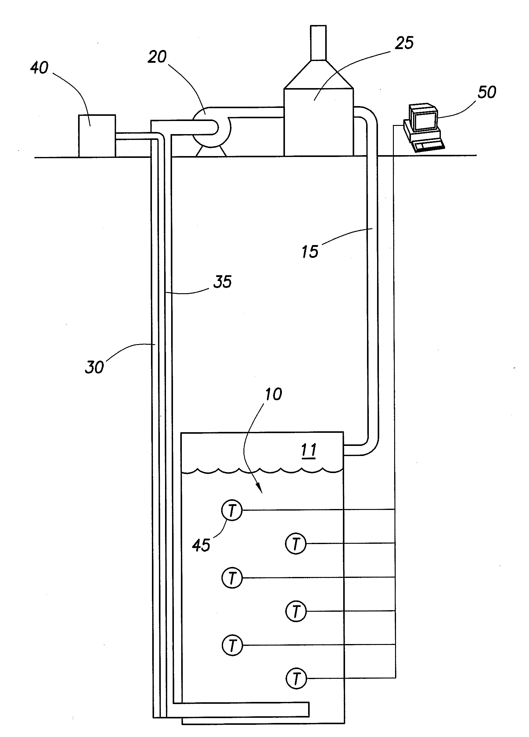
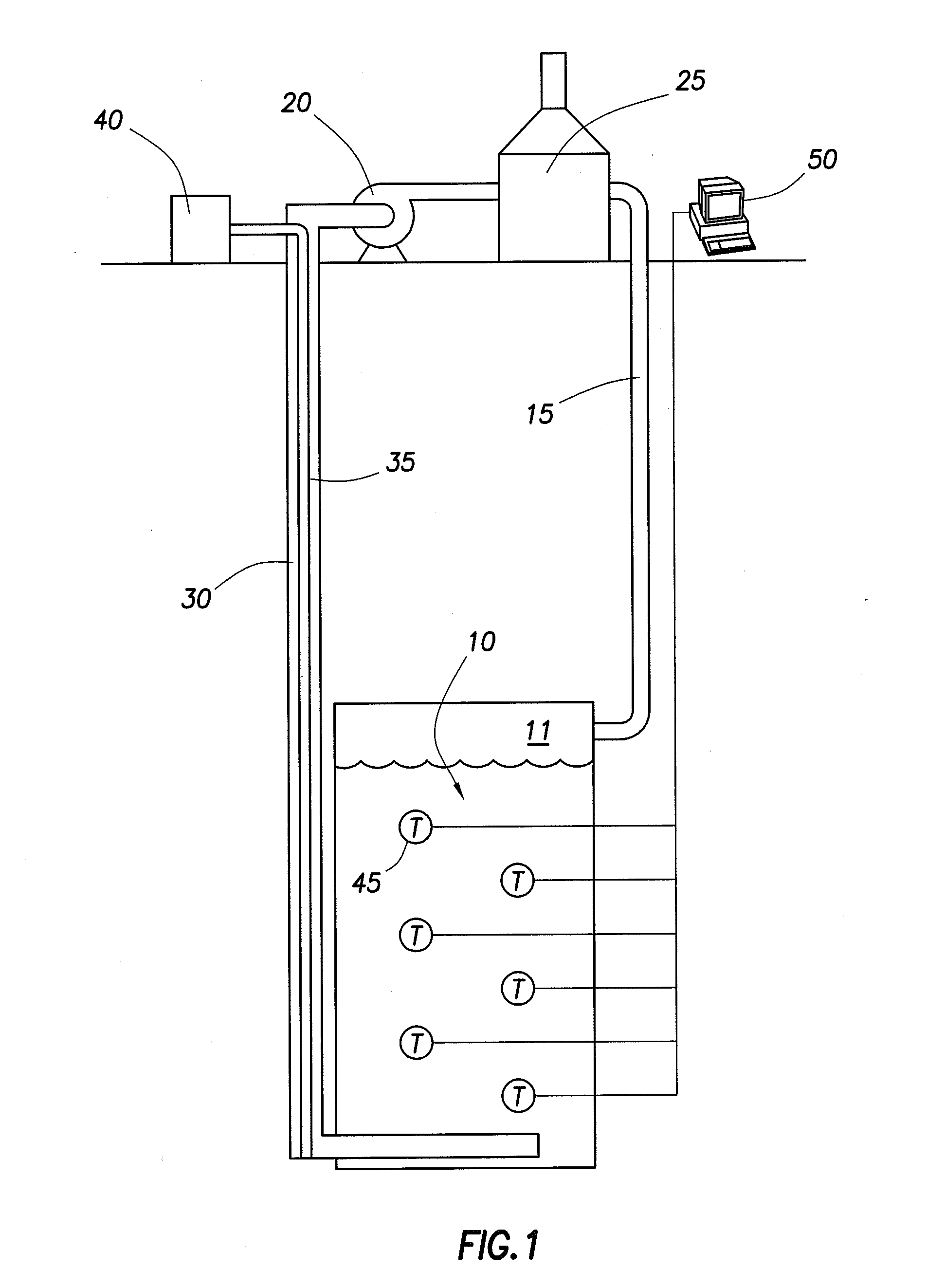
[0015]Turning to FIG. 1, an oil shale retort is generally indicated by the arrow 10. The retort 10 has been formed by removing a portion of the oil shale and then rubbilizing oil shale in a formation within a defined volume. The defined volume forms an underground retort or an in-situ retort and the rubbilizing is accomplished by drilling a pattern of holes into the formation and subjecting the formation to explosions which break up the formation. Preferably about 20% of the shale has been removed at various elevations with...


PUM


Abstract

This invention relates to recovering hydrocarbons from oil shale preferably in-situ where the temperature of the oil shale deposit is controlled to maximize recovery of hydrocarbons and minimize decomposition of carbonate minerals into carbon dioxide that might be released into the atmosphere. The process includes generating heat from hydrocarbon gases recovered from the oil shale and then later performing a controlled burn of the char that is left in the spent shale after the kerogens have been thermally cracked and the most of the recoverable hydrocarbons have been recovered. The burning of the char is also controlled based on the temperature of the oil shale in-situ, the temperature of the gases retuning to the surface from the oil shale and the carbon dioxide in the gases returning to the surface.

Description

CROSS-REFERENCE TO RELATED APPLICATIONS[0001]This application is a non-provisional application which claims benefit under 35 USC §119(e) to U.S. Provisional Application Ser. No. 61 / 156,266 filed Feb. 27, 2009, entitled “Recovery of Hydrocarbons From Oil Shale Deposits,” which is incorporated herein in its entirety.STATEMENT REGARDING FEDERALLY SPONSORED RESEARCH OR DEVELOPMENT[0002]NoneFIELD OF THE INVENTION[0003]This invention relates to the recovery of hydrocarbons from in ground oil shale reserves.BACKGROUND OF THE INVENTION[0004]The United States has an almost unimaginable volume of hydrocarbons locked up in huge reserves of oil shale. However, the current technology for recovering oil from oil shale has been a substantially expensive process that is only economically viable when crude oil prices are high. Shale does not have the energy density of coal with more than about 85% being rock.[0005]While mining the shale is discouraged by the cost, another technique for liberating th...

Claims


Application Information

Patent Timeline
Patent Type & Authority Applications(United States)
IPC IPC(8): E21B43/24
CPCE21B43/243E21B43/24
Inventor SADOK, RICHARD D.
Owner CONOCOPHILLIPS CO
Why Eureka
Try Eureka