
Process For Reducing The Loss Of Backing Gas When Welding Pipe

a technology of backing gas and welding pipe, which is applied in the direction of manufacturing tools, welding apparatus, other domestic objects, etc., can solve the problems of gas loss and detrimental to global productivity, and achieve the effect of reducing the loss of gas

Inactive Publication Date: 2010-09-02
AIR LIQUIDE IND US LP
View PDF35 Cites 9 Cited by
  • Summary
  • Abstract
  • Description
  • Claims
  • Application Information

AI Technical Summary

Problems solved by technology

An existing problem that exists during welding is that some of the gas that forms a backing is lost because it diffuses or passes through the plan of joint that is not yet welded.
This loss of gas is detrimental for the global productivity of the welding process as it leads to the waste (gas consumption) of expensive gases, such as helium or argon.

Method used


Image

  • Process For Reducing The Loss Of Backing Gas When Welding Pipe
  • Process For Reducing The Loss Of Backing Gas When Welding Pipe
  • Process For Reducing The Loss Of Backing Gas When Welding Pipe

Examples


Embodiment Construction

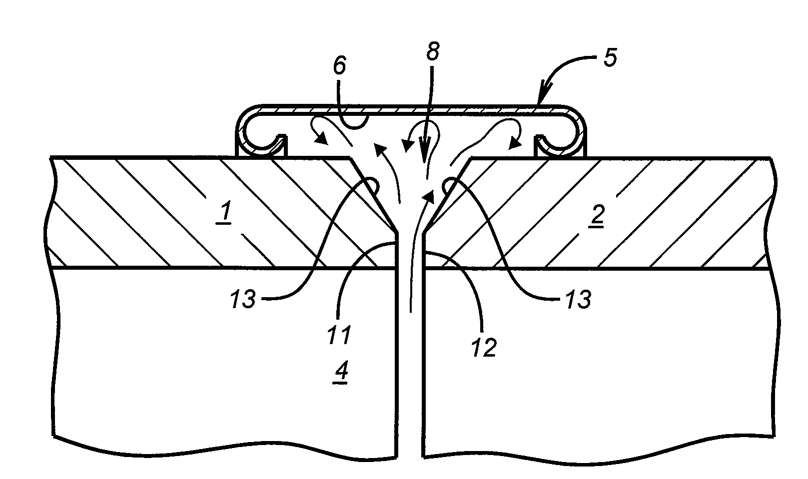
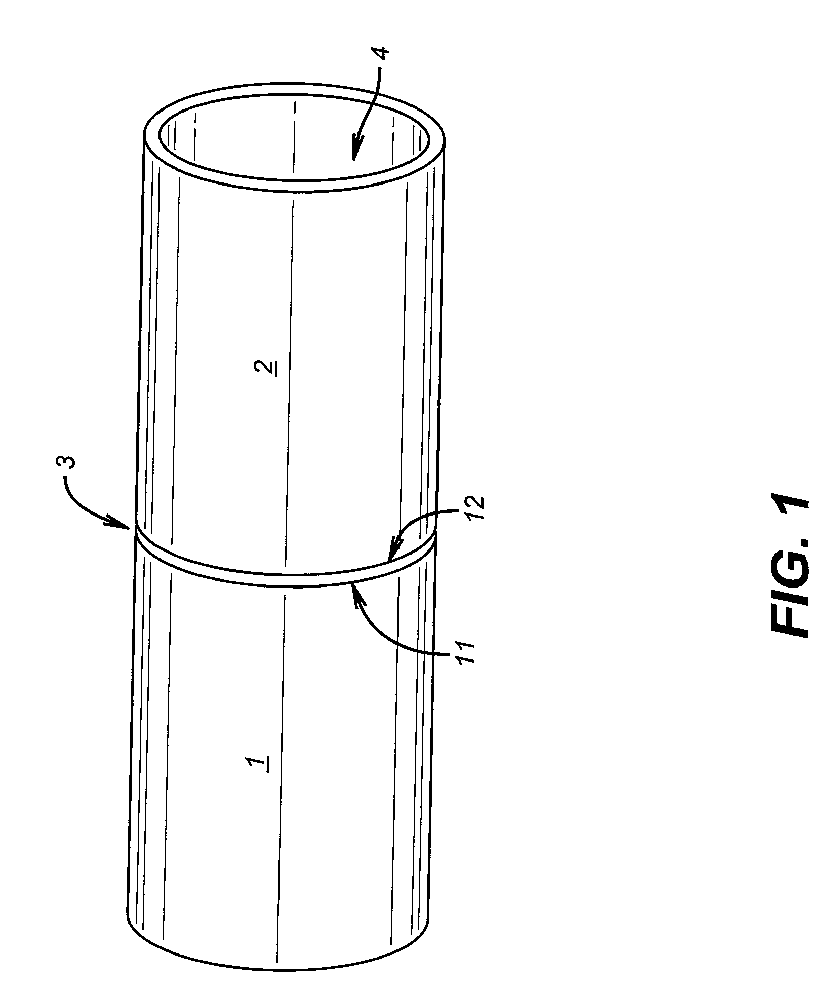
[0017]In one embodiment of the present invention, the process utilized comprises a first step of providing a first pipe that comprises a first free end and a second pipe that comprises a second free end with the first and second pipes having substantially the same outer diameter. While the term “pipe” is used herein, the term is meant to encompass not only hollow cylinders used to convey a material, but also other hollow devices that may be in a shape other than a cylindrical shape. In addition, the phrase “substantially the same outer diameter” refers to diameters of the first and second pipes that are the same or that have slight variations in diameter but are such that they may still be effectively welded together.

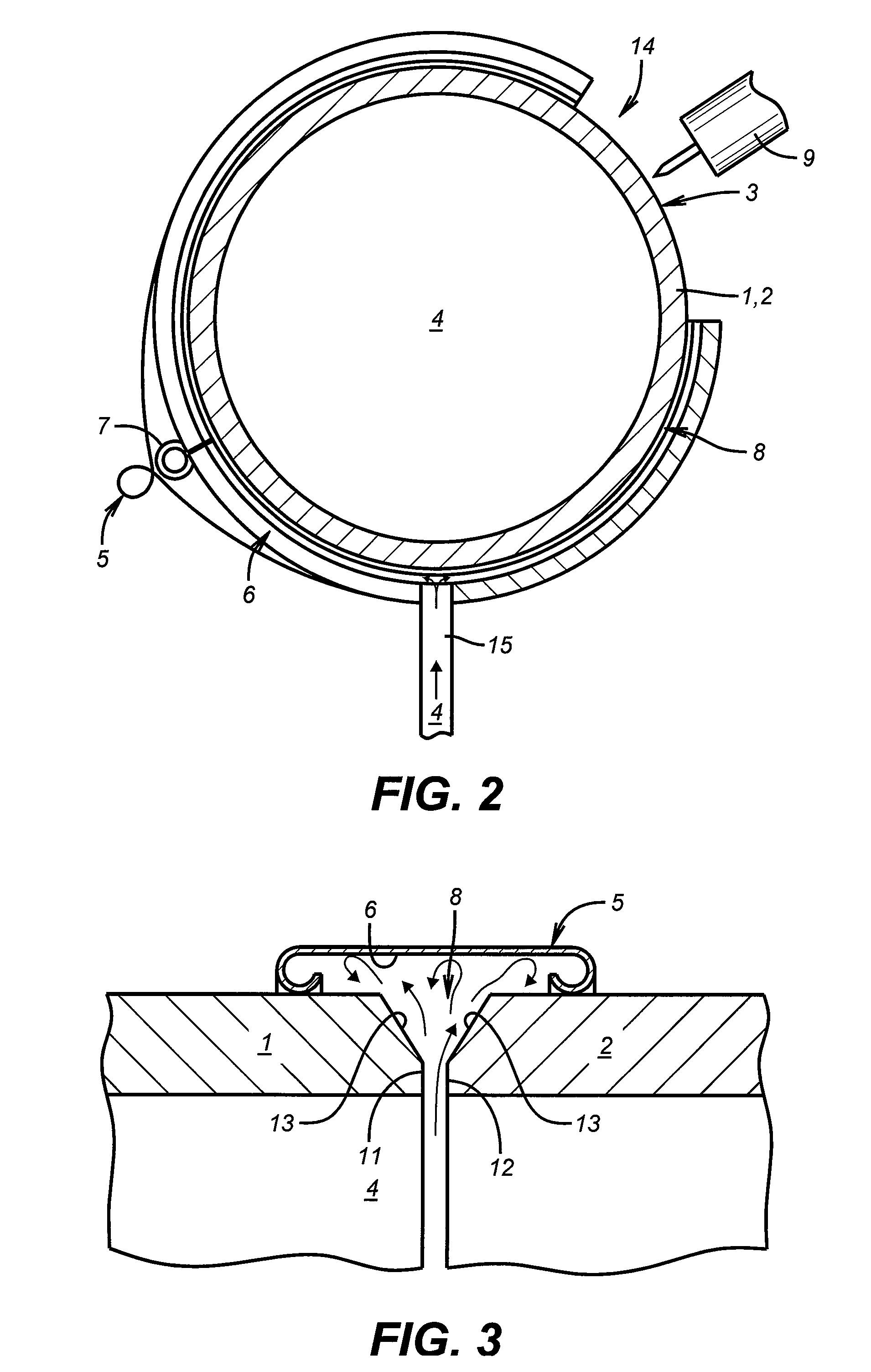
[0018]In the process, the first free end of the first pipe abuts the second free end of the second pipe in order to obtain a plan of joint to be welded. In order to minimize the loss of backing gas, a cover device comprising a gutter-shaped portion is provided. This cov...


PUM

PropertyMeasurementUnit
Resilienceaaaaaaaaaa

Abstract

The present invention provides for a process for welding pipes together utilizing a cover device that has a gutter-shaped portion that is arranged on the plan of joint of the pipes to be welded together. By arranging the cover device such that the gutter-shaped portion faces and covers a portion of the plan of joint formed by the abutment of the ends of the pipes to be welded together, it is possible to eliminate or minimize the waste of gas that is utilized to create an internal gas backing.

Description

FIELD OF THE INVENTION[0001]The present invention concerns a process for reducing the loss of backing gas when arc welding pipes together.BACKGROUND[0002]Metal pipes, tubes, pipelines, conduits, conduct and similar materials that have to be joined together are usually welded. More precisely, the end of one pipe is first abutted to the end of another pipe in order to obtain a plan of joint formed by the circular edges of the pipe ends. The ends of each pipe can be beveled so as to typically obtain a U-, V- or Y-shaped plan of joint. A circular weld joint is then welded along the circular plan of the joint by means of a welding torch, such as an electric arc welding torch or a laser torch. For protecting the welding bead during welding, i.e., the molten metal forming the welding joint after solidification, a backing gas, for example, an inert gas such as helium, argon, or reactive gases such as hydrogen or nitrogen, or mixtures thereof, is often introduced into the pipes.[0003]The com...

Claims


Application Information

Patent Timeline
IPC IPC(8): B23K9/00
CPCB23K2201/06B23K9/321B23K2101/06
Inventor SCHWEIGHARDT, FREDERICK
Owner AIR LIQUIDE IND US LP
Features
  • Generate Ideas
  • Intellectual Property
  • Life Sciences
  • Materials
  • Tech Scout
  • Unparalleled Data Quality
  • Higher Quality Content
  • 60% Fewer Hallucinations
Learn More