Power transmission apparatus

a technology of power transmission and transmission device, which is applied in the direction of asynchronous induction clutch/brake, electric device, propulsion by batteries/cells, etc., can solve the problems of increasing apparatus cost, reducing torque transmission capacity, and complicated apparatus configuration, so as to improve torque transmission capacity, prevent braking torque, and prevent braking torque

Active Publication Date: 2010-09-02
TOYOTA JIDOSHA KK +1
View PDF25 Cites 26 Cited by
  • Summary
  • Abstract
  • Description
  • Claims
  • Application Information

AI Technical Summary

Benefits of technology

[0008]The present invention has an advantage to improve the torque transmission capacity of a power transmission apparatus that can drive a load by transmitting the power of a prime mover to the load through an electromagnetic coupling between rotary elements, and can also drive the load with electric power supplied to a stationary element conductor. The present invention has another advantage, in the power transmission apparatus, to prevent a braking torque from acting on the load when the power of the prime mover is used to drive the load, without supplying electric power from an electric storage apparatus to a rotary element conductor.
[0025]The present invention can improve the torque transmission capacity because a torque acts between the first rotary element and the third rotary element, a torque acts between the first stationary element and the third rotary element, and a torque acts between the second stationary element and the second rotary element.
[0026]Moreover, according to the present invention, when the power of the prime mover is used to drive a load, the rotational speed of a prime mover side rotary element (one of the first rotary element and the second rotary element) can be maintained higher than the rotational speed of a load side rotary element (the other of the first rotary element and the second rotary element). Therefore, the present invention can prevent a braking torque from acting on the load side rotary element without supplying electric power to the rotary element conductor of the first rotary element from the electric storage apparatus via the electric power transmission unit. As a result, the present invention does not require any inverter to perform the bidirectional electric power conversion for the rotary element conductor of the first rotary element. Accordingly, the present invention can prevent the braking torque from acting on the load in the state where the power of the prime mover is used to drive the load without complicating the configuration of the power transmission apparatus and without increasing the cost of the apparatus.

Problems solved by technology

As a result, torque transmission capacity decreases.
If two inverters are provided, the configuration of the apparatus becomes complicated and the cost for the apparatus increases.

Method used


Image

  • Power transmission apparatus
  • Power transmission apparatus
  • Power transmission apparatus

Examples


first embodiment

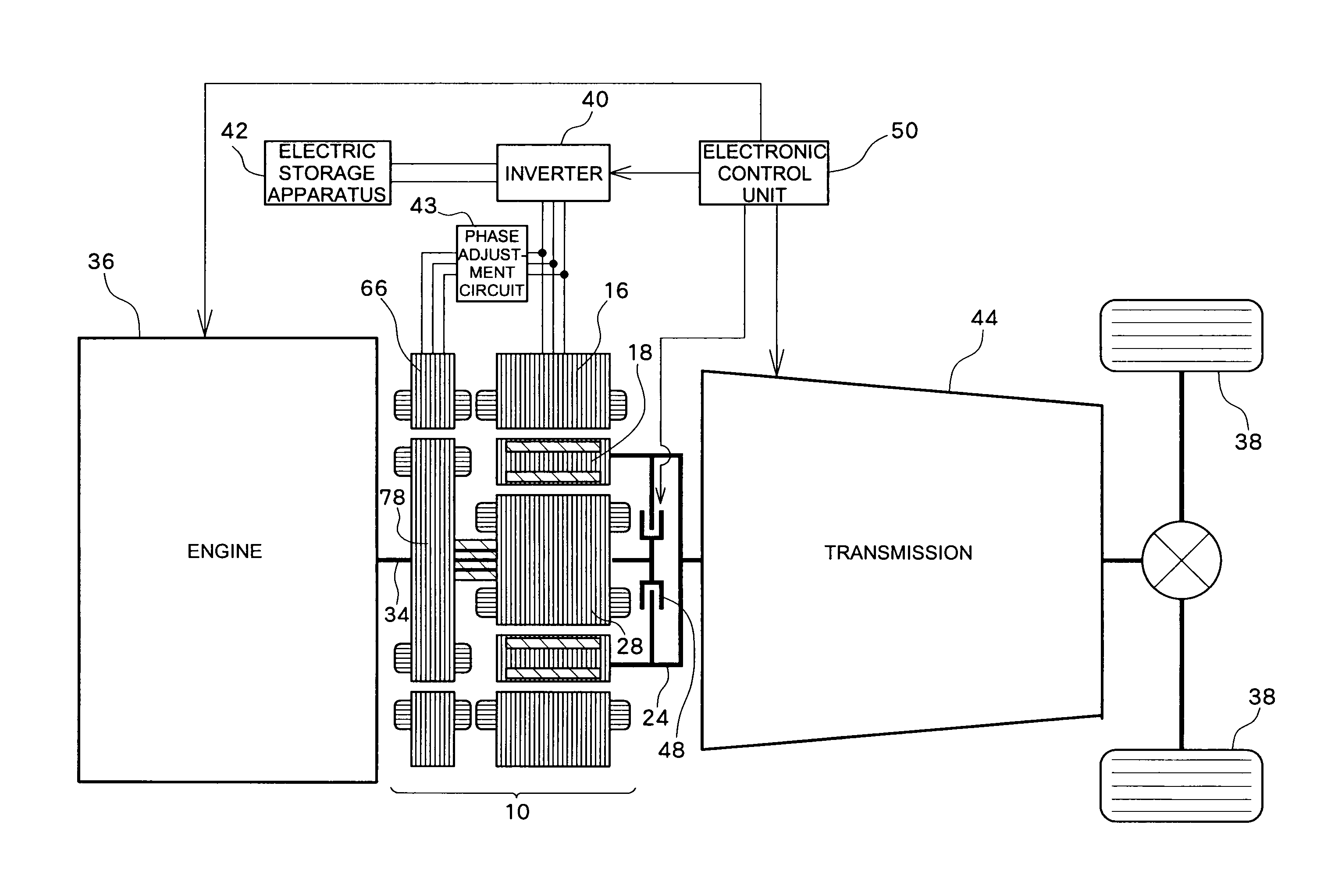
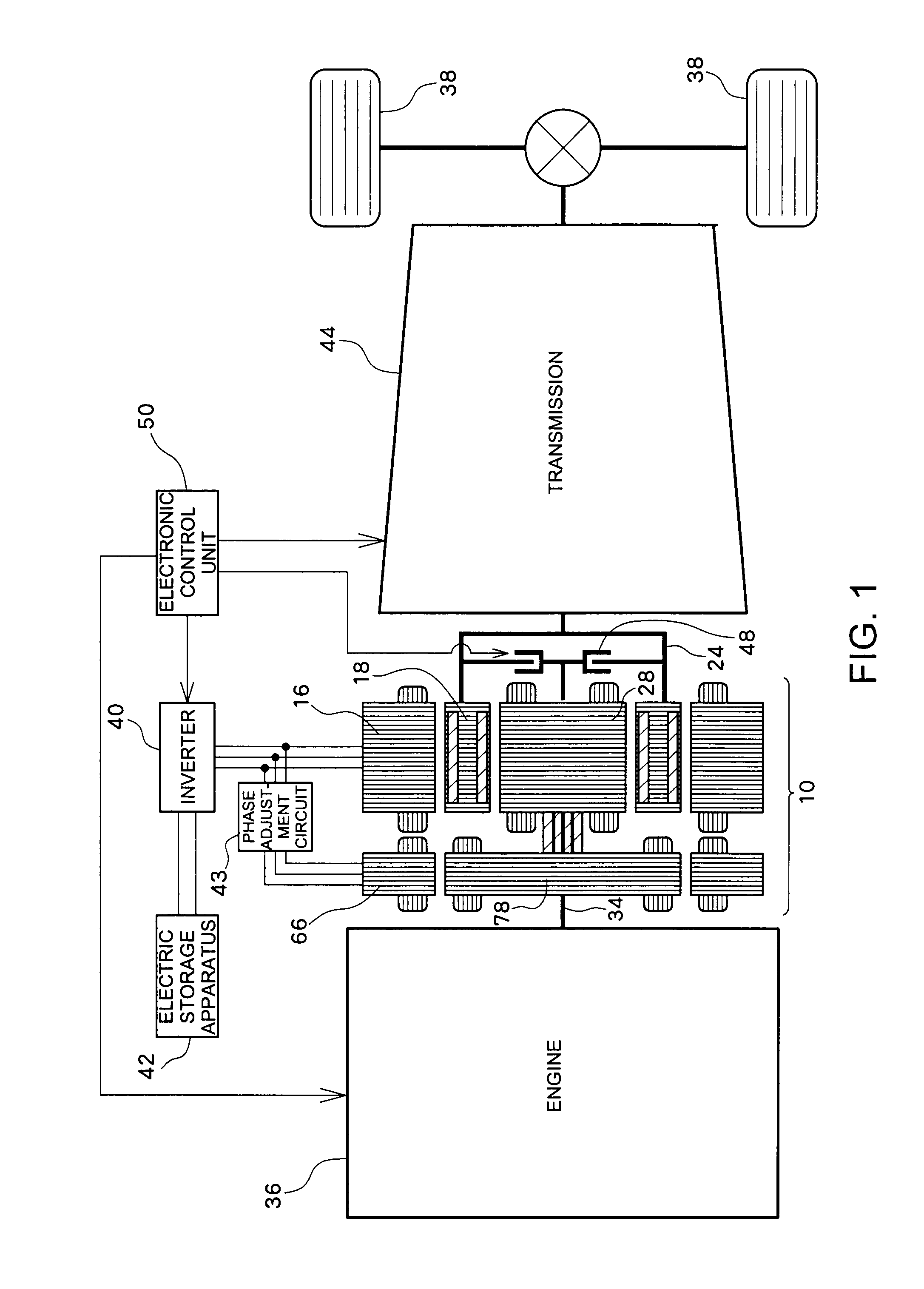
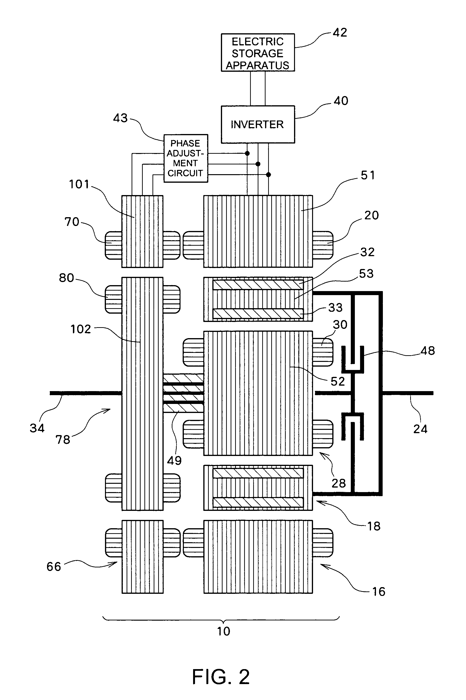
[0055]FIGS. 1 to 4 illustrate a schematic configuration of a hybrid driving apparatus including a power transmission apparatus according to a first embodiment of the present invention. FIG. 1 illustrates an overall configuration of the hybrid driving apparatus. FIGS. 2 to 4 illustrate a configuration of an electric rotary machine 10. The hybrid driving apparatus according to the present embodiment includes an engine (an internal combustion engine) 36 as a prime mover that can generate power (mechanical power), a transmission 44 provided between the engine 36 and wheels 38, and an electric rotary machine 10 provided between the engine 36 and the transmission 44. The hybrid driving apparatus according to the present embodiment can be used, for example, as a power output apparatus that can drive an automotive vehicle.

[0056]The electric rotary machine 10 includes a first stator (a first stationary element) 16 fixed to a casing (not illustrated), a first rotor (a first rotary element) 28...

second embodiment

[0097]FIGS. 15 and 16 illustrate a schematic configuration of a hybrid driving apparatus including a power transmission apparatus according to a second embodiment of the present invention. FIG. 15 illustrates an overall configuration of the hybrid driving apparatus. FIG. 16 illustrates a configuration of the electric rotary machine 10. In the following description of the second embodiment, components similar or corresponding to those described in the first embodiment are denoted by the same reference numerals and their descriptions are not repeated.

[0098]In the present embodiment, the electric rotary machine 10 includes a stator 216 fixed to a casing (not illustrated), a first rotor 228 that is disposed on the radial inner side of the stator 216 and can rotate relative to the stator 216, and a second rotor 218 that is disposed between the stator 216 and the first rotor 228 and can rotate relative to the stator 216 and the first rotor 228. As the first rotor 228 is mechanically conne...


PUM


Abstract

A rotational difference is generated between a first and a second rotor and a third rotor, which causes an induced current to flow in a first rotor winding. This causes a torque to act between the first rotor and the third rotor. The rotary magnetic field generated by the induced current flowing through a second rotor winding interacts with a second stator, which in turn generates an induced electromotive force in a second stator winding. The induced electromotive force is applied via a phase adjustment circuit to a first stator winding, which generates a rotary magnetic field and causes a torque to act between the first stator and the third rotor. The rotary magnetic field generated by the second rotor winding and the induced current flowing in the second stator winding causes a torque to act between the second stator and the second rotor.

Description

TECHNICAL FIELD[0001]The present invention relates to a power transmission apparatus, and more particularly relates to a power transmission apparatus that can drive a load by transmitting power of a prime mover to the load through an electromagnetic coupling between rotary elements, and can drive the load with electric power supplied to a stationary element conductor.BACKGROUND ART[0002]The following Patent Literature 1 discloses this kind of power transmission apparatus. The power transmission apparatus disclosed in Patent Literature 1 includes a first rotor having a magnet and mechanically connected to driving wheels, a second rotor having a winding electromagnetically coupled with the magnet of the first rotor and mechanically connected with an engine (prime mover), a stator having a winding electromagnetically coupled with the magnet of the first rotor, a transformation-rotor having a winding electrically connected to the winding of the second rotor and mechanically connected to...

Claims


Application Information

Patent Timeline
Patent Type & Authority Applications(United States)
IPC IPC(8): H02K49/04H02K47/00B60L50/15B60L50/16
CPCB60K1/02B60L2210/30B60K6/543B60K2006/262B60L11/123B60L11/14B60L15/2054B60L2220/42B60L2240/421B60L2240/423B60W10/08B60W20/00B60W2510/081B60W2710/083H02K16/025H02K17/36H02K51/00Y02T10/6217Y02T10/6243Y02T10/641Y02T10/646Y02T10/7077Y02T10/7241Y02T10/7275Y02T10/7216Y02T10/648H02K47/00B60L2210/40B60L2220/52B60L2210/10B60K6/448B60K6/26B60K6/365B60K6/48B60K2006/4833B60W10/06B60L50/16B60L50/61H02K7/006H02K7/116H02K16/00Y02T10/62Y02T10/64Y02T10/70Y02T10/7072Y02T10/72B60K6/22B60K6/36B60W10/10B60W20/30B60W20/15
Inventor WATANABE, TAKAOTSUCHIYA, EIJINISHIZAWA, HIROYUKIKITAHATA, TAKESHI
Owner TOYOTA JIDOSHA KK
Why Eureka
Try Eureka