Display Device, Electro-Optical Element Driving Method and Electronic Equipment

a technology of electrooptical elements and drive systems, applied in static indicating devices, instruments, organic semiconductor devices, etc., can solve the problems of difficulty in implementing a large high-definition display device, simple matrix display device, etc., and achieve the effect of reducing the power consumption of the display device as a whole and reducing the power consumption of the horizontal drive system adapted to supply the input signal voltage vsig to each pixel via a signal lin

Inactive Publication Date: 2010-09-02
SONY CORP
View PDF8 Cites 3 Cited by
  • Summary
  • Abstract
  • Description
  • Claims
  • Application Information

AI Technical Summary

Benefits of technology

[0010]As is clear from the formula (2), if the capacitance value Coled of the organic EL element is sufficiently larger than the capacitance value Ccs of the holding capacitance, the increment ΔVs of the source potential Vs of the drive transistor can be suppressed when the gate potential Vg of the drive transistor rises. That is, when sufficiently larger than the capacitance value Ccs of the holding capacitance, the capacitance value Coled of the organic EL element is advantageous in providing a large gate-to-source potential difference of the drive transistor.
[0011]The reason for this is as follows. That is, if a large gate-to-source potential difference of the drive transistor can be provided at the time of writing of the input signal voltage Vsig by the write transistor, the amplitude of the input signal voltage Vsig written to the pixel can be reduced to the same extent. Hence, power consumption of horizontal drive system adapted to supply the input signal voltage Vsig to each pixel via a signal line can be reduced. As a result, the display device as a whole can be reduced in power consumption.
[0012]In light of the foregoing, it is an object of the present invention to provide a display device which permits the capacitance value of the electro-optical element such as organic EL element to be arbitrarily set without changing the light extraction efficiency of the pixel, and to provide an electro-optical element driving method and electronic equipment.

Problems solved by technology

It should be noted, however, that a simple matrix display device has some problems although simple in construction.
Such problems include such as difficulty in implementing a large high-definition display device.

Method used


Image

  • Display Device, Electro-Optical Element Driving Method and Electronic Equipment
  • Display Device, Electro-Optical Element Driving Method and Electronic Equipment
  • Display Device, Electro-Optical Element Driving Method and Electronic Equipment

Examples


application examples

[0100]The display device according to the present invention described above is applicable as a display device of electronic equipment across all fields including those shown in FIGS. 7 to 11, namely, a digital camera, laptop personal computer, mobile terminal device such as mobile phone and video camcorder. These pieces of equipment are designed to display an image or video of a video signal fed to or generated inside the electronic equipment. Examples of electronic equipment to which the present invention is applied will be described below.

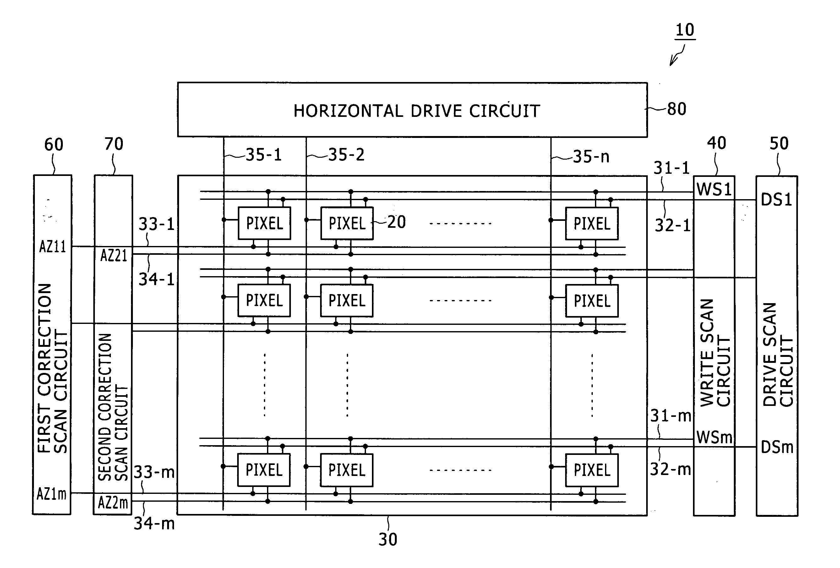
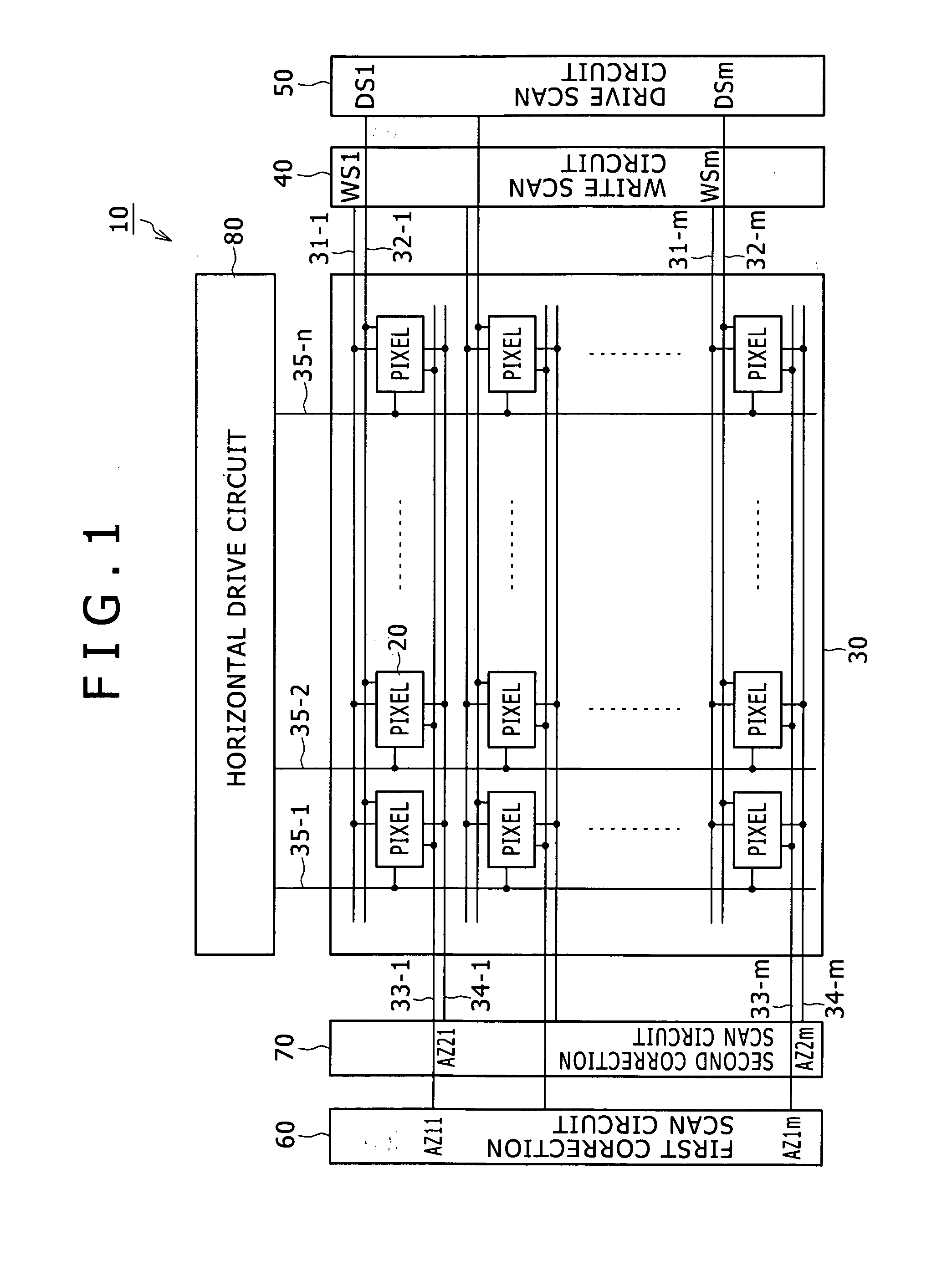
[0101]It should be noted that the display device according to the present invention includes that in a modular form having a sealed configuration. For example, such a display device corresponds to a display module formed by attaching an opposed section made, for example, of transparent glass to the pixel array section 30. The aforementioned light-shielding film may be provided on the transparent opposed section, in addition to films such as color...


PUM


Abstract

The present invention permits a capacitance value of an electro-optical element such as organic EL element to be arbitrarily set without changing the light extraction efficiency of a pixel. That is, the present invention permits a capacitance value Coled of an organic EL element (21) to be arbitrarily set by adjusting the light emission area of the organic EL element (21) without changing the light extraction efficiency of a pixel (20) in an organic EL display device. The organic EL display device has the pixels (20) arranged in a matrix form. A light extraction opening (56) is formed on the surface of the pixel with a light-shielding film (black matrix) (57). The light extraction opening (56) has an opening area smaller than the light emission area of the organic EL element (21).

Description

TECHNICAL FIELD[0001]The present invention relates to a display device having pixels, containing an electro-optical element, arranged in a matrix form, and to an electro-optical element driving method and electronic equipment.BACKGROUND ART[0002]In recent years, in the field of image display device for displaying images, organic EL display devices having a number of pixel circuits, containing an electro luminescence element, i.e., organic EL element, which is a so-called current-driven electro-optical element whose light emission brightness changes in accordance with current value flowing through the element, arranged in a matrix form have been developed and commercialized.[0003]An organic EL element is self-luminous. As a result, an organic EL display device offers several advantages compared with a liquid crystal display device which controls the light intensity from the light source (backlight) by means of pixels, containing liquid crystal cells such as high image visibility, no ...

Claims


Application Information

Patent Timeline
Patent Type & Authority Applications(United States)
IPC IPC(8): G09G5/10
CPCG09G3/3233G09G2330/023G09G2300/0842G09G2300/0861G09G2310/0256G09G2320/043H01L27/3265H01L51/5284H01L2251/5315H01L27/1255G09G2300/0408G09G2300/0439G09G2300/0809G09G2310/0294G09G2300/0819H10K59/1216H10K50/865H10K2102/3026H05B33/12H05B33/14G09G3/30G09G2300/0404H01L27/124H01L27/15
Inventor TOMIDA, MASATSUGU
Owner SONY CORP
Why Eureka
Try Eureka