Method and apparatus for producing nanofibers and polymeric webs

Inactive Publication Date: 2009-05-21
PANASONIC CORP
View PDF5 Cites 23 Cited by
  • Summary
  • Abstract
  • Description
  • Claims
  • Application Information

AI Technical Summary

Benefits of technology

[0013]A method for producing nanofibers of the present invention includes the steps of: supplying a polymer solution, which is prepared by dissolving a polymeric substance in a solvent, into a rotating container having a plurality of small holes, at least a portion of which in the vicinity of the small holes possessing conductivity; rotating the rotating container; and applying an electric field to filaments of the polymer solution discharged from the small holes and allowing them to be drawn by a centrifugal force and an electrostatic explosion associated with an evaporation of the solvent to produce nanofibers made of the polymeric substance. It should be appreciated that, in the present invention, in order to apply an electric field to the filaments of the polymer solution discharged from the small holes of the rotating container, a large potential difference is applied between the rotating container and an object or a member that constitutes a space for forming nanofibers between itself and the rotating container. For example, when such an object or a member that constitutes a space for forming nanofibers between itself and the rotating container is either the earth or a member such as the collector grounded to the earth, a positive or negative high voltage with reference to the ground potential is applied to the rotating container. When a high voltage that is either positive or negative with reference to the ground potential is applied to a member such as the collector that constitutes a space for forming nanofibers between itself and the rotating container, the rotating container may be grounded or a high voltage of the opposite polarity may be applied to the rotating container. The small holes are not limited to those directly punched through the circumferential wall of the rotating container. Needless to say, the small hole may be provided by a nozzle member installed on or integrally molded with the circumferential wall of the rotating container. Also, the rotating container as a whole may possess conductivity. According to the present invention, the polymer solution is supplied into the rotating container such that the polymer solution forms a layer along the circumferential wall of the rotating container, whereby the polymer solution is discharged from the small holes by centrifugal force. This eliminates the need for applying pressure to the polymer solution, and simplifies the supply of the polymer solution to the rotating container.
[0014]According to the structure described above, a polymer solution is discharged as filaments from a plurality of small holes of the rotating container under the influence of the centrifugal force and is electrically charged by an applied electric field. When doing so, since the polymer solution is drawn first under the influence of the centrifugal force, the polymer solution is discharged from the small holes stably, and electrical interference hardly occur since the rotating container is rotated to discharge the polymer solution from the small holes radiately by the centrifugal force. Since electrical interference does not affect the condition, the polymer solution can be drawn reliably and effectively even if the small holes are densely disposed. Then, as the charged filaments of the polymer solution are further drawn by the centrifugal force with their diameters decreasing further and with the solvent evaporating, the electric charges start to concentrate. At the time when Coulomb force exceeds the surface tension, a primary electrostatic explosion takes place, and the polymer solution is explosively drawn. As the evaporation of the solvent proceeds further, a secondary electrostatic explosion takes place in a similar manner and the polymer solution is explosively drawn. A tertiary electrostatic explosion may take place, depending on the situation, so that the polymer solution is drawn further. Accordingly, nanofibers made of a polymeric substance and having a submicron diameter can be efficiently produced from a polymer solution discharged as filaments from a plurality of small holes.
[0015]Furthermore, since the small holes can be densely disposed as described above, a large amount of nanofibers can be efficiently produced using a simple and compact structure. Furthermore, since the polymer solution discharged from the small holes is first drawn by the centrifugal force, those small holes need not be made to be extremely small, whereby the polymer solution is discharged from the small holes stably to produce nanofibers uniformly. Thus, it is only necessary that the rotating container be simply provided with small holes. Hence, the rotating container can be fabricated easily and at low costs, and the maintenance can still be conducted easily even though there are a large number of small holes.

Problems solved by technology

However, since, in the conventional electrospinning, only a plurality of nanofibers can be produced from the tip of a single nozzle, the productivity in producing highly porous polymeric webs cannot be improved as desired, and its production cannot be realized.
However, this method had inherent technical difficulty in producing nanofibers and is only capable of producing fibers whose diameters are large compared to those of nanofibers of the submicron order.
As a result, the deposition distribution of nanofibers on the collector 46 becomes extremely sparse at the central area and concentrated at the peripheral area, thereby failing to produce a uniform polymeric web.
Therefore, the above-mentioned arrangement is not sufficiently effective in uniforming the deposition distribution.
In addition to this, the concentration of the evaporated solvent may increase in the vicinity of the nozzles so that the insulation weakens, and accordingly, corona discharge takes place, thereby failing to form fibers.
Furthermore, if a number of nozzles 41 are to be disposed, it is difficult to supply a liquid polymeric substance evenly to each of the nozzles 41.
This may complicate the structure of the apparatus and raise the cost of facility.
However, it is also extremely difficult to conduct the maintenance on a number of long and narrow nozzles 41 in order to ensure that they are constantly in a proper condition.

Method used


Image

  • Method and apparatus for producing nanofibers and polymeric webs
  • Method and apparatus for producing nanofibers and polymeric webs
  • Method and apparatus for producing nanofibers and polymeric webs

Examples


embodiment 1

[0054]Embodiment 1 of a method and an apparatus for producing a polymeric web will be described with reference to FIGS. 1 to 7B.

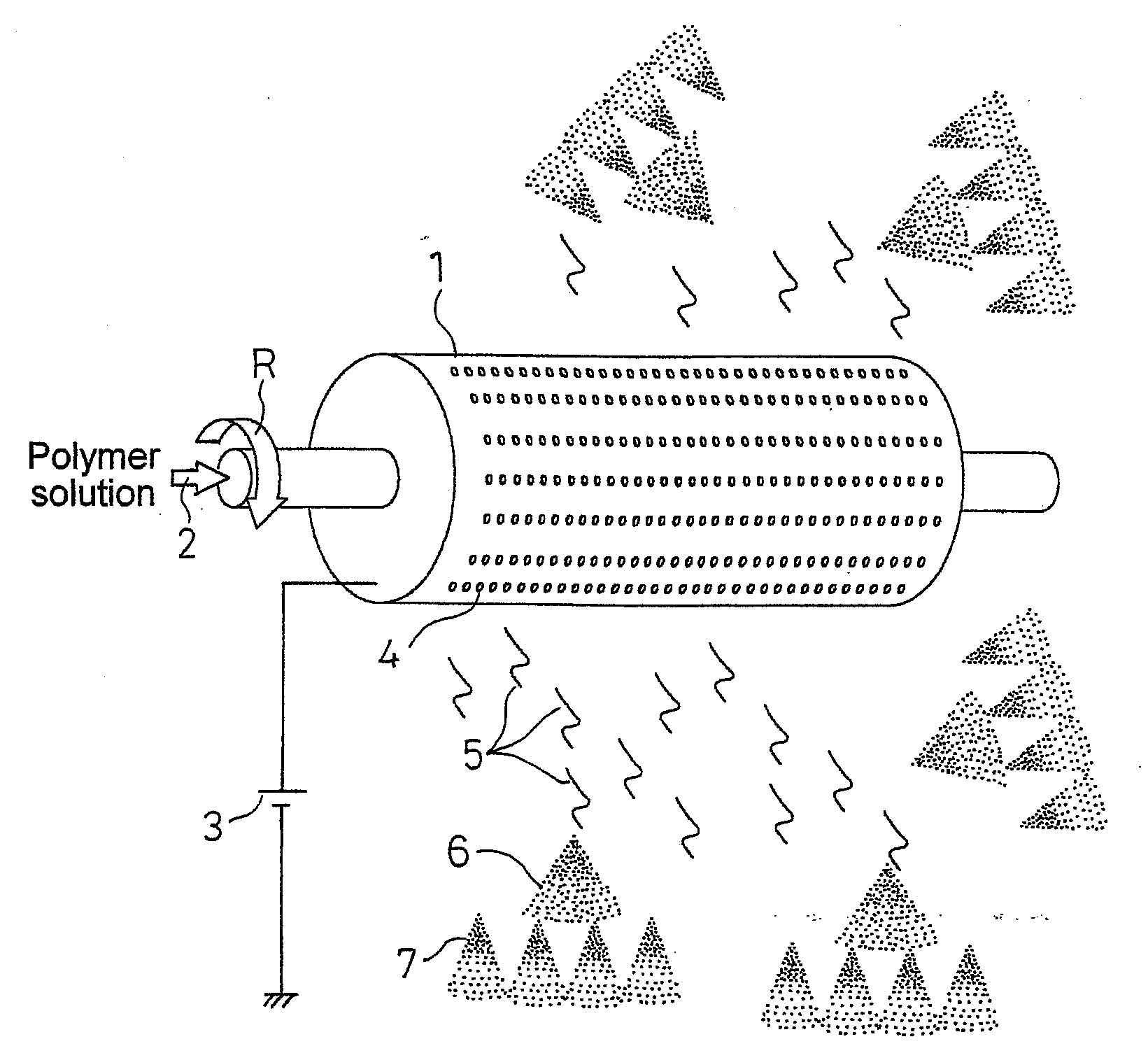
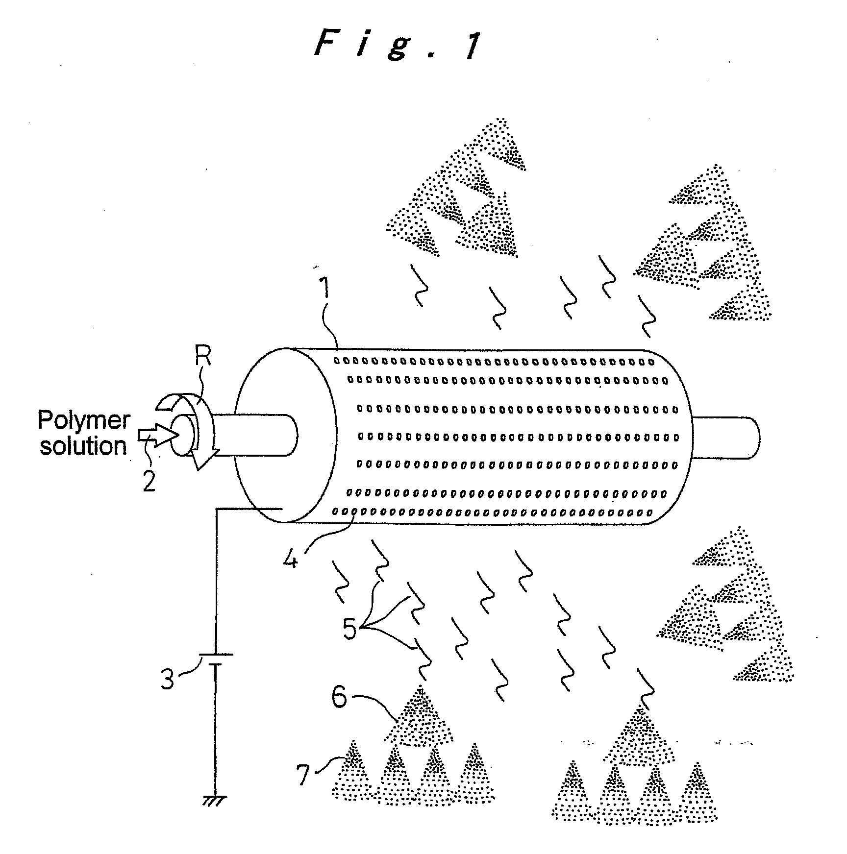
[0055]FIG. 1 is an explanatory diagram illustrating a principle of a method for producing nanofibers, the method being applied to a method for producing a polymeric web of the present embodiment. In FIG. 1, reference numeral 1 designates a cylindrical container, as a rotating container, having a diameter of 20 to 500 mm. The rotating container is driven to rotate at a rate of 30 to 6000 rpm about the rotation axis as shown by an arrow R. The rotating container 1 is supplied with a polymer solution 2 from one end thereof. In this instance, the polymer solution is obtained by dissolving a polymeric substance, which is a material for the nanofibers, in a solvent.

[0056]Examples of polymeric substances constituting polymer solution 2 include polypropylene, polyethylene, polystyrene, polyethylene oxide, polyethylene terephthalate, polybutylene terephthalate, poly...

embodiment 2

[0069]Next, embodiment 2 concerning a method and an apparatus for producing a polymeric web of the present invention will be described with reference to FIG. 8. In the following description of the embodiment, the same components as appeared in the preceding embodiment will be designated by the same reference numerals, and descriptions of those components will be omitted while only differences will be described.

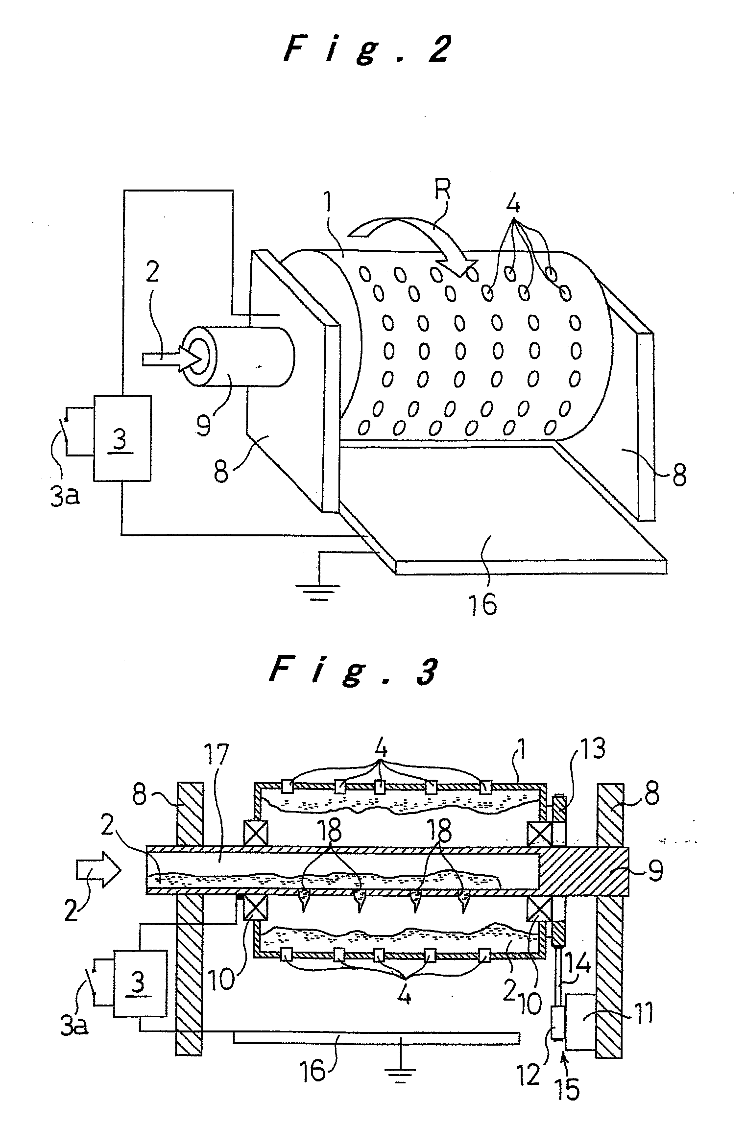
[0070]In the above-described embodiment, an example was illustrated where the center shaft 9 was secured on the support members 8, and the cylindrical container 1 is rotatably supported by the bearings 10 around this center shaft 9. However, in the present embodiment, the cylindrical container 1 is secured onto the center shaft 9, and both ends of the center shaft 9 are rotatably supported by the support members 8 with the bearings 10 interposed therebetween as illustrated in FIG. 8. Accordingly, the rotation drive means 15 is configured such that the output shaft of the drive...

embodiment 3

[0072]Next, embodiment 3 concerning a method and an apparatus for producing a polymeric web of the present invention will be described with reference to FIG. 9.

[0073]In the above-described embodiments, examples were illustrated in which a high voltage with respect to the ground potential generated by the high voltage generating means 3 was applied to the cylindrical container 1, with the collector 16 being maintained at the ground potential. However, in the present embodiment, a high voltage that is either positive or negative and generated by the high voltage generating means 3 is applied to the collector 16, and the cylindrical container 1 is grounded through the conductive member 29 and the bearings 10.

[0074]In the present embodiment, too, the polymeric filaments 5 are discharged from the cylindrical container 1 that is maintained at a high voltage either positively or negatively relative to the collector 16. Then, a polymer solution forming these polymeric filaments 5 becomes el...


PUM

PropertyMeasurementUnit
Electrical conductivityaaaaaaaaaa
Speedaaaaaaaaaa
Electric potential / voltageaaaaaaaaaa

Abstract

A polymer solution that is prepared by dissolving a polymeric substance in a solvent is supplied into a cylindrical container serving as a rotating container having a plurality of small holes. The cylindrical container is driven to rotate by rotation drive means, and an electric field is applied by high voltage generating means to polymeric filaments discharged from the small holes so that they become electrically charged. Then, primary and secondary electrostatic explosions associated with the centrifugal force and the evaporation of the solvent take place, drawing the polymeric filaments and producing nanofibers made of the polymeric substance. These nanofibers are deposited to produce a polymeric web. Accordingly, by employing a simple structure, nanofibers and a polymeric web utilizing them can be produced evenly with excellent productivity.

Description

TECHNICAL FIELD[0001]The present invention relates to a method and an apparatus for producing nanofibers made of polymeric substances and a highly porous polymeric web obtained by depositing those nanofibers.BACKGROUND ART[0002]Conventionally, electrospinning (electric charge induced spinning) is known as a method for producing nanofibers made of polymeric substances and having a diameter in a submicron order. In the conventional electrospinning, a polymer solution is supplied to a needle nozzle to which a high voltage is applied so that the polymer solution discharged as filaments from this needle nozzle is electrically charged. As a solvent of the polymer solution evaporates, a distance between these electric charges decreases, and Coulomb force acting thereon increases. When this Coulomb force exceeds the surface tension of the filamentous polymer solution, the filamentous polymer solution undergoes what is called an electrostatic explosion where it is drawn explosively. This phe...

Claims


Application Information

Patent Timeline
IPC IPC(8): B29C47/66
CPCD01D5/18D01D5/0069B82Y40/00D01D5/00D04H3/16
Inventor TAKAHASHI, MITSUHIRO
Owner PANASONIC CORP
Why Eureka
Try Eureka