
Communication apparatus

a communication apparatus and propagation channel technology, applied in the field of communication apparatuses, can solve the problems of affecting the accuracy of demodulation, and affecting the demodulation performance of components, so as to reduce the spread of waveforms and reduce signal distortion

Inactive Publication Date: 2010-09-02
SHARP KK
View PDF8 Cites 13 Cited by
  • Summary
  • Abstract
  • Description
  • Claims
  • Application Information

AI Technical Summary

Benefits of technology

The present invention relates to a communication apparatus and a method for estimating the propagation channel of an OFDM communication system. The invention aims to improve the accuracy of demodulation and reduce the impact of noise on the demodulation performance. The invention proposes a method for reducing the distortion caused by the time window used for processing the pilot symbol and the DFT / IDFT method used for frequency conversion. The invention also proposes a method for adding an auxiliary pilot subcarrier to the pilot symbol to improve the accuracy of propagation channel estimation. The technical effects of the invention include improved demodulation accuracy and reduced impact of noise on the demodulation performance.

Problems solved by technology

The noise component thus directly affects the accuracy of the demodulation.
In particular, in QAM (Quadrature Amplitude Modulation) modulation, noise in an amplitude direction degrade demodulation performance and cause problems.
However, if DFT / IDFT processing points fail to match the number of subcarriers in the signal as in the case where guard bands are contained in the signal on the grounds, for example, the performance of an analog filter, the time filter process may disadvantageously cause the edges of a signal band to be distorted.
This in turn corresponds to cutoff of a part of a widely extended impulse waveform shown in FIG. 9(a), resulting in loss of information in the original signal.
This may result in distortion during propagation channel estimation.
In this system, when the propagation channel is estimated by the DFT method using a pilot symbol 1003 with a uniform amplitude all over the band used by data symbols, the band edges are distorted, thus reducing the accuracy of estimation of the band edges as shown in FIG. 10(b).
A DFT / IDFT process requires a large amount of arithmetic operation.

Method used


Image

  • Communication apparatus
  • Communication apparatus
  • Communication apparatus

Examples


first embodiment

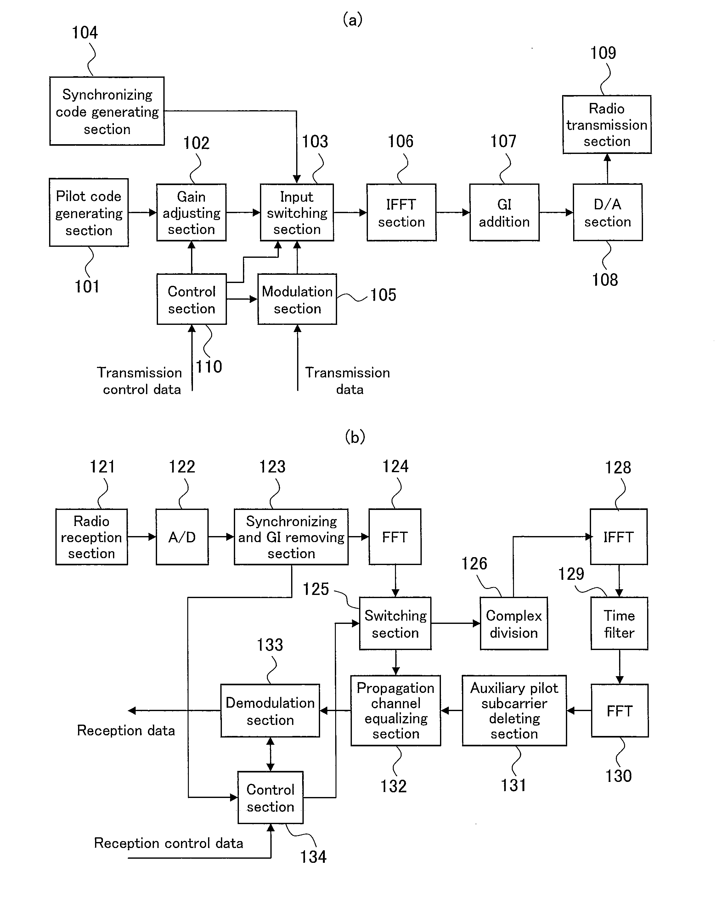
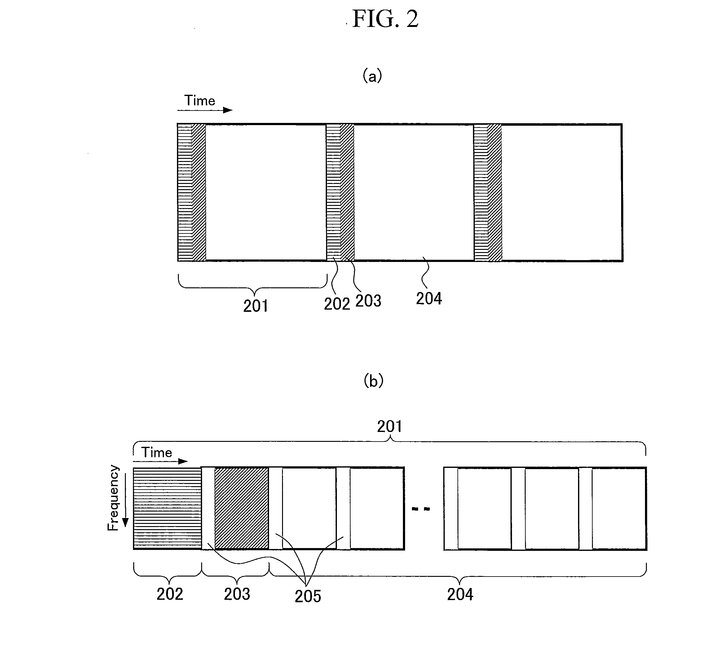
[0043]A communication technique according to the present invention will be described with reference to the drawings. First, the spectrum of a pilot symbol with auxiliary pilot subcarriers added, which is used in the present embodiment, will be described. The pilot symbol actually used is multiplied by a certain code on the frequency domain for whitening to use a signal with reduced PAPR. However, for simplification of description, the core for whitening is omitted.

[0044]First, the spectrum of a pilot symbol that uses a conventional auxiliary pilot subcarrier and the waveform of the pilot symbol on the time domain will be described. FIG. 3(a) schematically shows the spectrum of a pilot symbol that uses conventional auxiliary pilot subcarriers. Auxiliary pilot subcarrier 302 are located at both of the opposite ends of a pilot subcarriers 301 in a signal band and adjacent to the pilot subcarriers 301. A DFT / IDFT processing band is denoted by reference numeral 303. A guard band 304 in w...

second embodiment

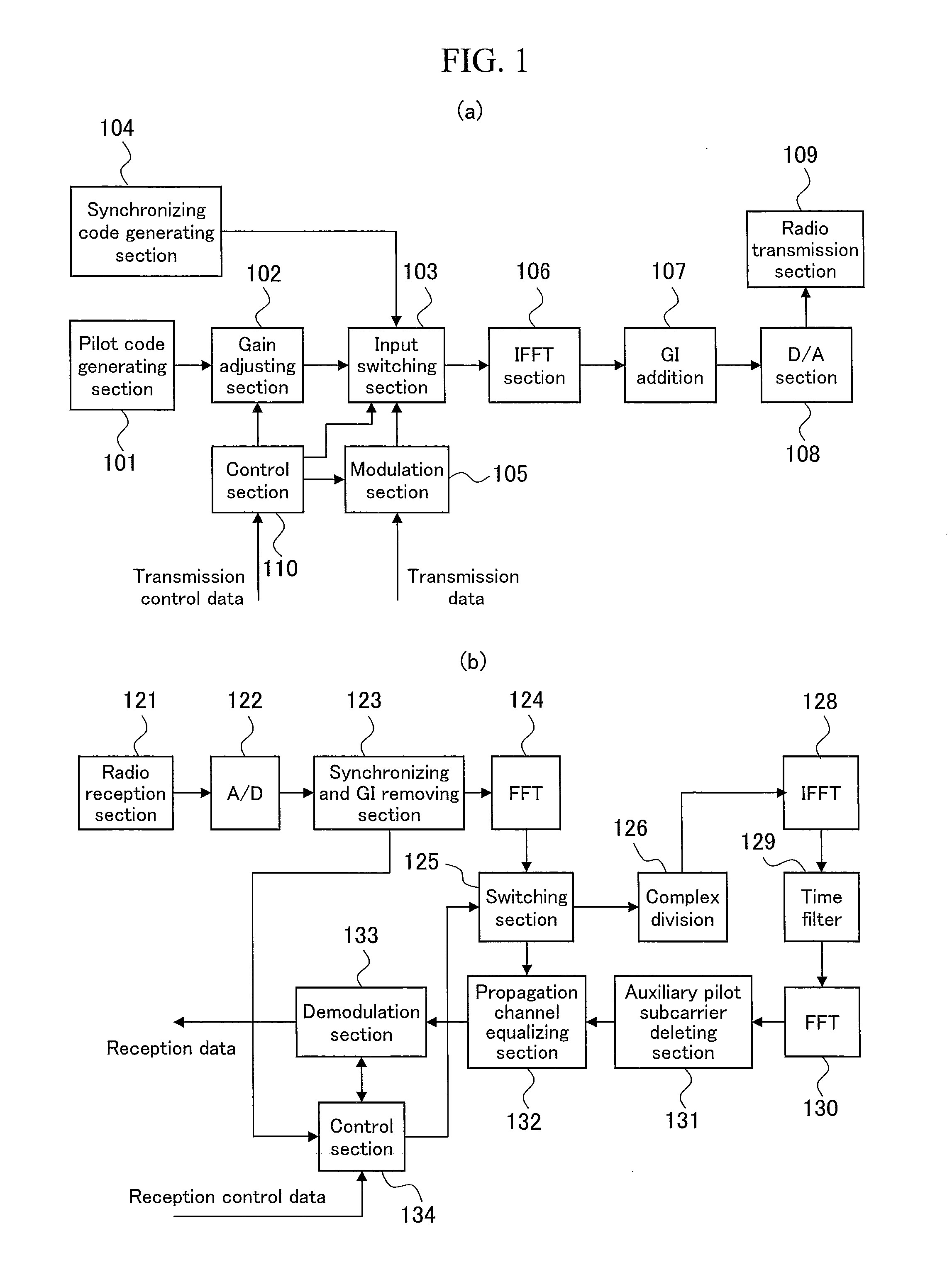
[0076]Now, the present invention will be described with reference to the drawings. As described above, the attenuation characteristic of the auxiliary pilot subcarrier depends on relevant parameters and the circumstances under which the auxiliary pilot subcarriers are used, and cannot be uniquely determined. The present embodiment illustrates an example of the configuration of communication apparatuses that control the attenuation characteristic of the auxiliary pilot subcarriers depending on the circumstances of the propagation channel between the communication apparatuses.

[0077]First, control performed in the communication apparatuses according to the present embodiment will be described in brief. The amount by which the propagation channel estimation accuracy is improved based on the DFT method is determined by the amount by which the time filter removes the signals. Hence, the amount of time required to pass signals through a time filter, that is, the time window period, is as s...

third embodiment

[0095]Now, a communication technique according to the present invention will be described with reference to the drawings.

[0096]In the first and second embodiments, before a pilot symbol with auxiliary pilot subcarriers added is transmitted, the spectrum is corrected to improve the propagation channel estimation accuracy and the transmission power efficiency.

[0097]In the present embodiment, a method for exerting effects similar to those of the first and second embodiments on the receiver side if auxiliary pilot subcarriers according to the conventional method are added, that is, auxiliary pilot subcarriers with a rectangular spectrum are added. This method fails to improve the transmission power efficiency but improves the propagation channel estimation accuracy equivalently to the methods shown in the first and second embodiments. The transmission apparatus may be configured similarly to the conventional example shown in FIG. 11(a).

[0098]FIG. 8 is a function block diagram showing an...


PUM


Abstract

When in-phase data with an amplitude of 1 is located in each subcarrier, the envelope waveform of a time domain signal contains guard band 304 in an IDFT processing band. Thus, the waveform is such that a side lobe 306 is widely extended around the position of a point in time 0, as shown in FIG. 3(c). To allow the side lobe 306 to be suppressed, the amplitude of each band end of a transmission spectrum is smoothly reduced. Then, in a communication apparatus, the extension of the waveform on a time domain can be reduced by optimizing the spectrum of auxiliary pilot subcarriers.

Description

TECHNICAL FIELD[0001]The present invention relates to a communication apparatus, and in particular, to a propagation channel estimation technique for OFDM communication apparatuses.BACKGROUND ART[0002]In recent years, much effort has been made to study OFDM communication techniques. When an OFDM signal is received, a frequency equalization process is executed before a demodulation process in order to eliminate the adverse effects of a propagation channel. Propagation channel information is required for the frequency equalization process.[0003]The following method is generally used to obtain propagation channel information. A transmitter transmits a known pilot symbol. A receiver converts the received pilot symbol into a frequency domain signals. The frequency domain signals change into a frequency response divided by a code used in the transmission. Thus, a frequency response is obtained from the propagation channel.[0004]However, according to the above-described method, a noise com...

Claims


Application Information

Patent Timeline
Patent Type & Authority Applications(United States)
IPC IPC(8): H04L27/28
CPCH04L5/0007H04L5/0048H04L25/0216H04L25/03828H04L2025/03522H04L27/2626H04L27/2647H04L2025/03414H04L27/2613H04L27/26265
Inventor NAMBA, HIDEOHAMAGUCHI, YASUHIROTOH, SHIMPEIYOKOMAKURA, KAZUNARI
Owner SHARP KK
Learn More