Energy storage device with porous electrode

a technology of energy storage device and electrode, which is applied in the direction of wound/folded electrode electrode, sustainable manufacturing/processing, electrolytic capacitor manufacturing, etc., can solve the problems of insufficient mechanical flexibility and too expensive to produce desired battery form factor, and achieve the effect of large surface area and low cos

Inactive Publication Date: 2010-09-02
APPLIED MATERIALS INC
View PDF12 Cites 36 Cited by
  • Summary
  • Abstract
  • Description
  • Claims
  • Application Information

AI Technical Summary

Problems solved by technology

However, the process and structure described by Shin et al. is based on processing of silicon wafers to make large area electrodes—this is too expensive, undesirable for HVM and is not sufficiently mechanically flexible to produce desired battery form factors.

Method used

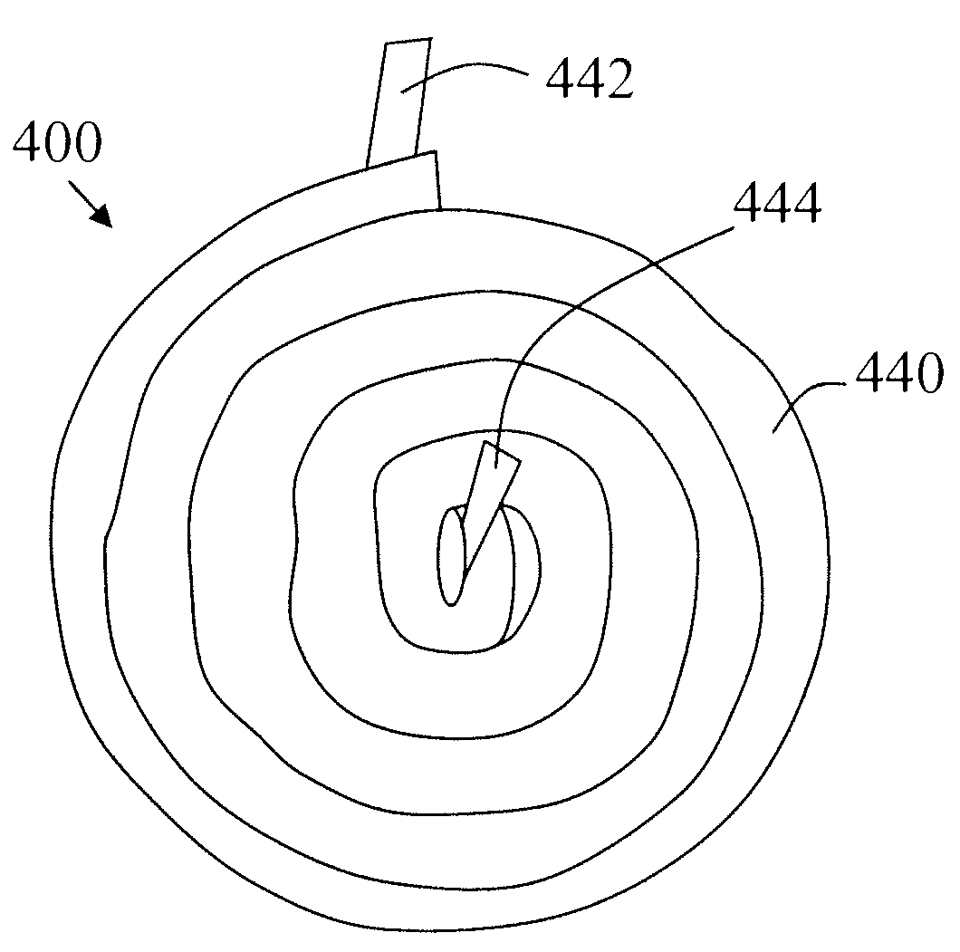
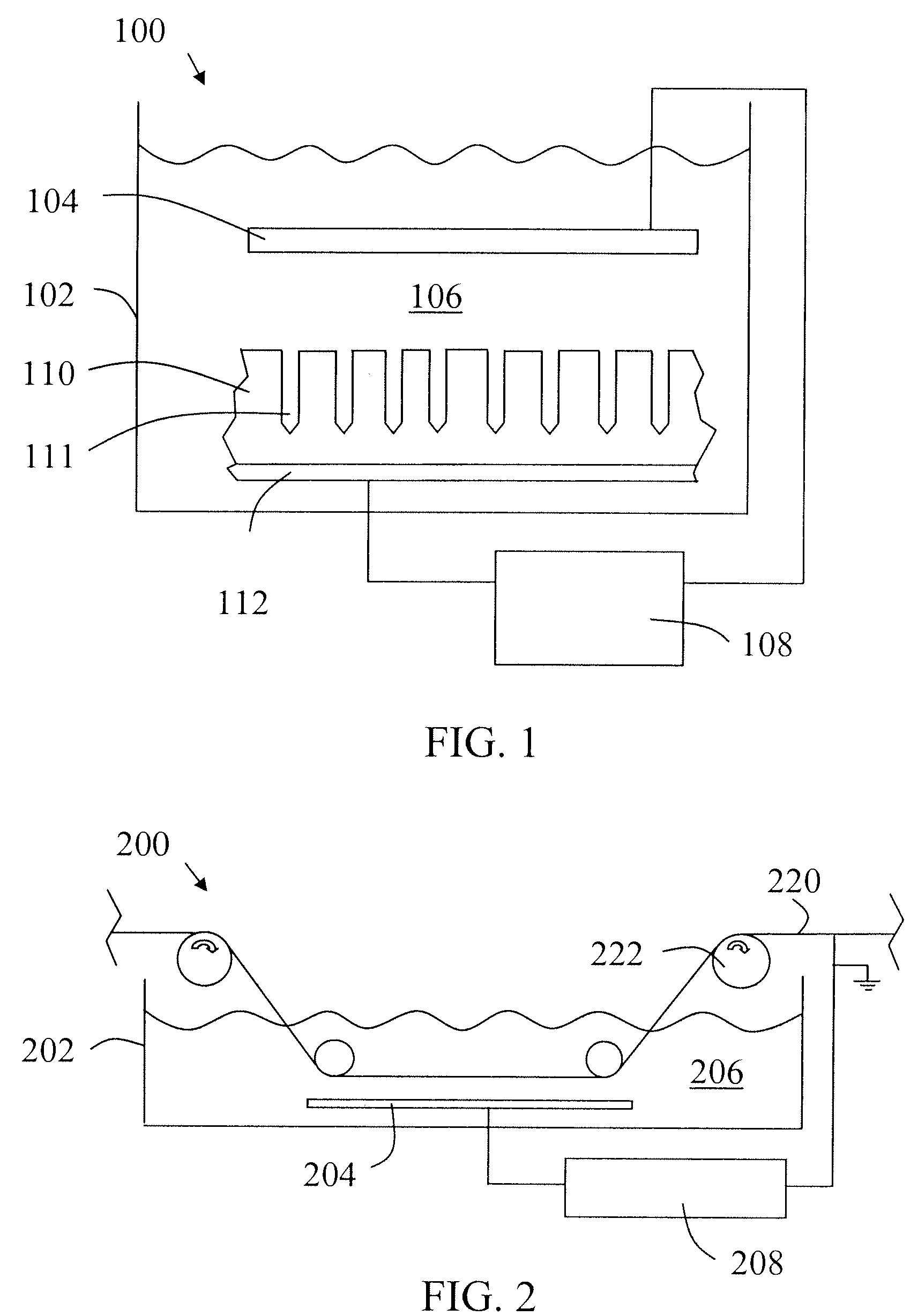
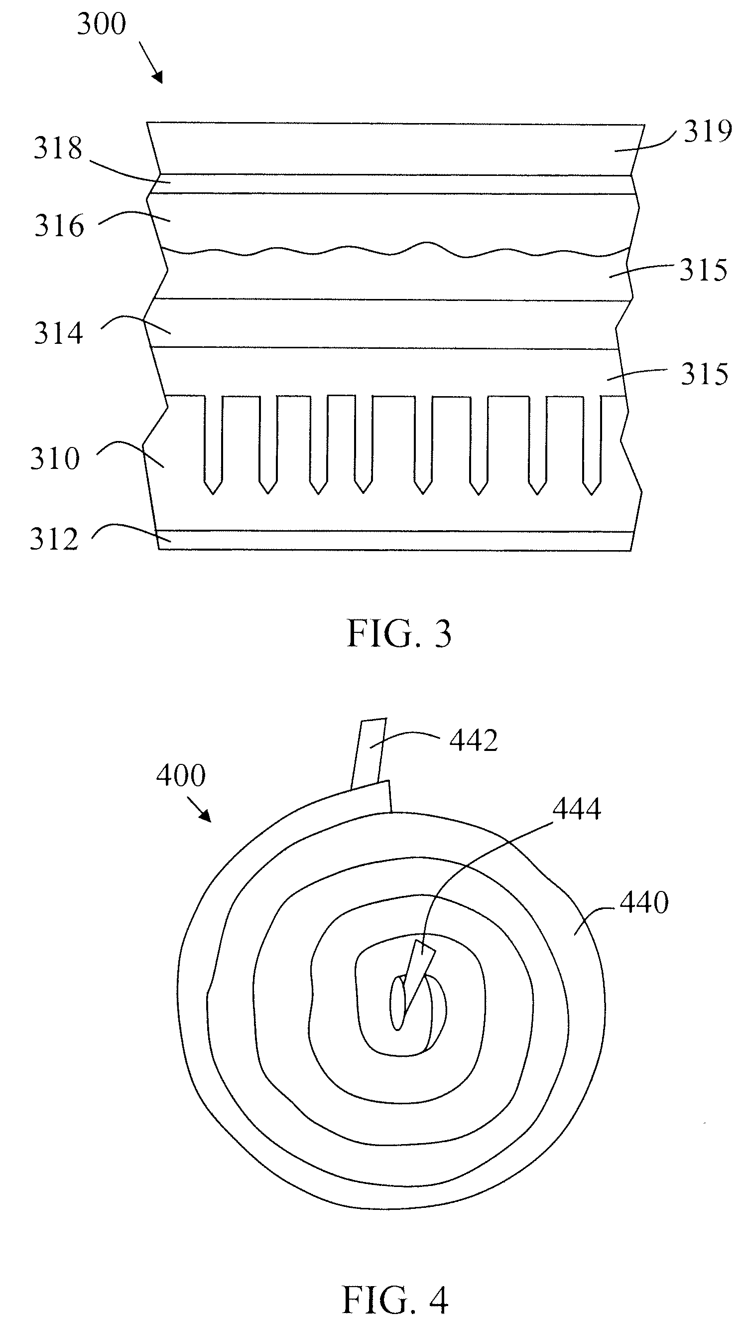

Image

  • Energy storage device with porous electrode
  • Energy storage device with porous electrode
  • Energy storage device with porous electrode

Examples


Embodiment Construction

[0013]The present invention will now be described in detail with reference to the drawings, which are provided as illustrative examples of the invention so as to enable those skilled in the art to practice the invention. Notably, the figures and examples below are not meant to limit the scope of the present invention to a single embodiment, but other embodiments are possible by way of interchange of some or all of the described or illustrated elements. Moreover, where certain elements of the present invention can be partially or fully implemented using known components, only those portions of such known components that are necessary for an understanding of the present invention will be described, and detailed descriptions of other portions of such known components will be omitted so as not to obscure the invention. In the present specification, an embodiment showing a singular component should not be considered limiting; rather, the invention is intended to encompass other embodimen...


PUM

PropertyMeasurementUnit
surface areaaaaaaaaaaa
electrically conductiveaaaaaaaaaa
semiconductoraaaaaaaaaa

Abstract

A method of fabricating an energy storage device with a large surface area electrode comprises: providing an electrically conductive substrate; depositing a semiconductor layer on the electrically conductive substrate, the semiconductor layer being a first electrode; anodizing the semiconductor layer, wherein the anodization forms pores in the semiconductor layer, increasing the surface area of the first electrode; after the anodization, providing an electrolyte and a second electrode to form the energy storage device. The substrate may be a continuous film and the electrode of the energy storage device may be fabricated using linear processing tools. The semiconductor may be silicon and the deposition tool may be a thermal spray tool. Furthermore, the semiconductor layer may be amorphous. The energy storage device may be rolled into a cylindrical shape. The energy storage device may be a battery, a capacitor or an ultracapacitor.

Description

FIELD OF THE INVENTION[0001]The present invention relates generally to energy storage devices, and more specifically to energy storage devices with porous electrodes.BACKGROUND OF THE INVENTION[0002]All solid state Thin Film Batteries (TFB) are known to exhibit several advantages over conventional battery technology such as superior form factors, cycle life, power capability and safety. However, there is a need for cost effective and high-volume manufacturing (HVM) compatible fabrication technologies to enable broad market applicability of TFBs. Further, there is a need to improve the performance of TFBs. One approach for improving TFB performance is to increase battery electrode surface area without impacting the battery size. There is a need for methods for increasing TFB performance which are compatible with HVM and are low cost.[0003]An approach for increasing electrode surface area by anodizing a silicon wafer to produce a porous electrode is described by Shin et al., “Porous s...

Claims


Application Information

Patent Timeline
Patent Type & Authority Applications(United States)
IPC IPC(8): H01M4/00C25D11/02H01G11/26
CPCC25D11/32H01G9/0032H01G9/055H01G9/07H01G11/86H01M10/0587H01G11/26H01G11/28H01G9/048H01M4/0404H01M4/134Y02E60/13Y02E60/10Y02P70/50H01G9/042H01M10/0431
Inventor NALAMASU, OMKARAMVERHAVERBEKE, STEVEN
Owner APPLIED MATERIALS INC
Why Eureka
Try Eureka