Polar modulation transmitter, adaptive distortion compensation processing system, polar modulation transmission method, and adaptive distortion compensation processing method

a technology of distortion compensation and transmitter, applied in the direction of power amplifier, power amplifier, amplifier with control circuit, etc., can solve the problems of inability to deal with adaptive processing and difficulty in increasing power efficiency, and achieve the effect of increasing the distortion compensation processing data capacity, low distortion characteristic, and increasing the circuit scal

Active Publication Date: 2010-09-02
PANASONIC CORP
View PDF12 Cites 68 Cited by
  • Summary
  • Abstract
  • Description
  • Claims
  • Application Information

AI Technical Summary

Benefits of technology

[0112]According to the invention, there can be provided a polar modulation transmitter that can realize low distortion characteristic of a power amplifier at the amplitude modulation operation time, at the modulation speed switching time, etc., while suppressing an increase in the distortion compensation processing data capaci

Problems solved by technology

Therefore, if a conventional quadrature modulation system is applied to the linear modulation system, it is difficult to increase the power efficiency.
In the polar modulation system, it is difficult at the present technological level to ensure the linearity of the output voltage amplitude relative to the input control voltage of a power amplifier for the required dynamic rang

Method used


Image

  • Polar modulation transmitter, adaptive distortion compensation processing system, polar modulation transmission  method, and adaptive distortion compensation processing method
  • Polar modulation transmitter, adaptive distortion compensation processing system, polar modulation transmission  method, and adaptive distortion compensation processing method
  • Polar modulation transmitter, adaptive distortion compensation processing system, polar modulation transmission  method, and adaptive distortion compensation processing method

Examples


first embodiment

[0188]A first embodiment of the invention describes an adaptive predistortion compensation processing technology for characteristic change of a power amplifier caused by environmental temperature change of a wireless communication apparatus, etc., without the need for a synchronization adjustment circuit for synchronizing an input baseband signal and an output signal of the power amplifier.

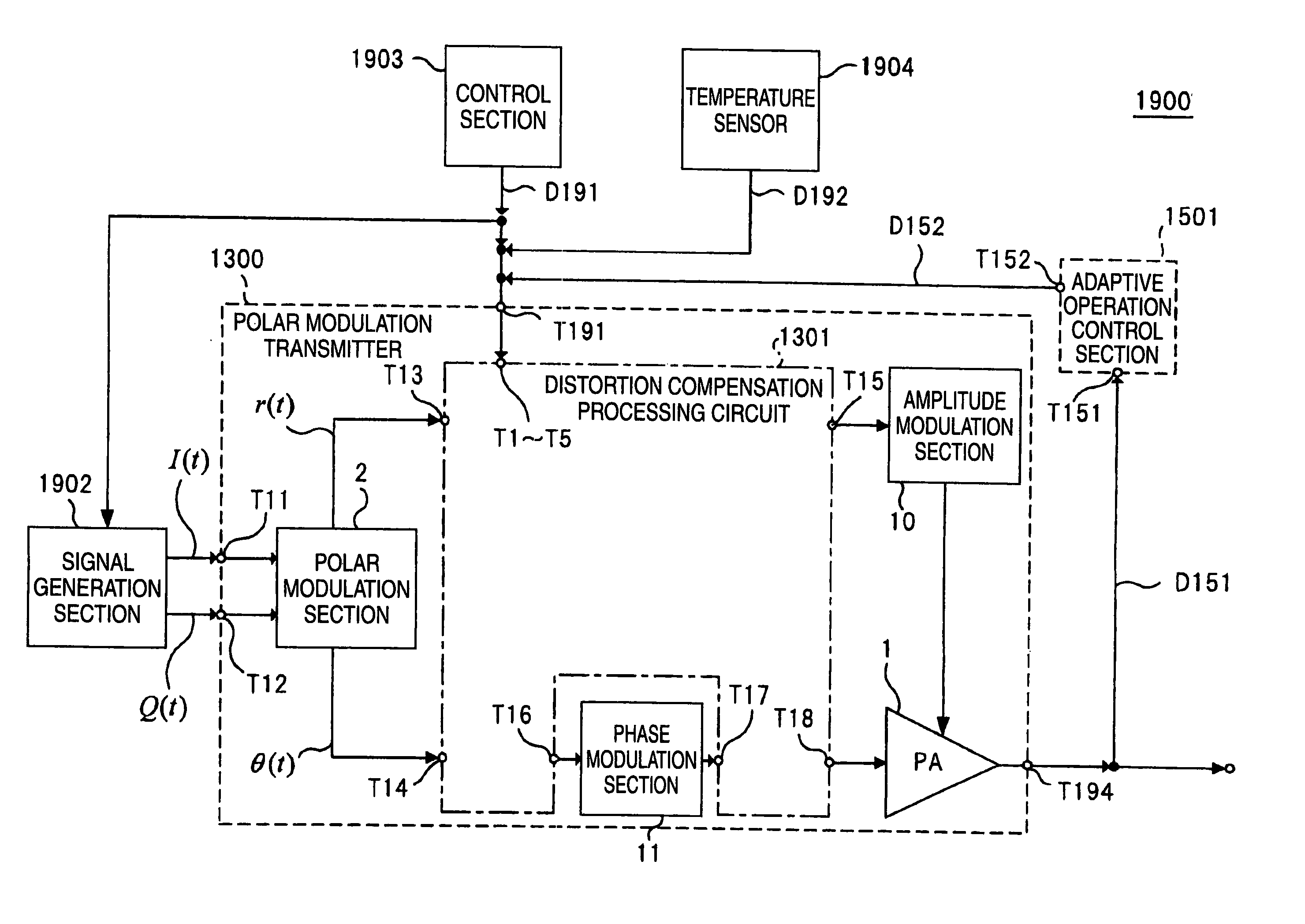
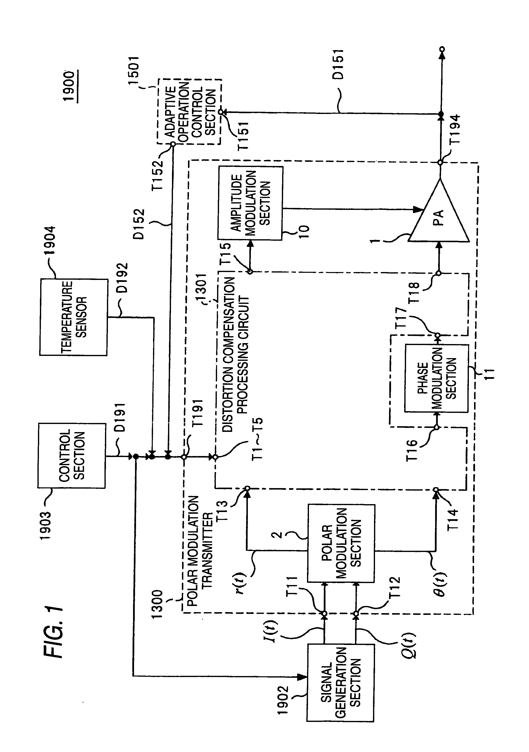
[0189]FIG. 1 is a diagram to show the schematic configuration of a transmission section of a wireless communication apparatus using a polar modulation transmitter according to the first embodiment of the invention.

[0190]As shown in FIG. 1, a wireless communication apparatus transmission section 1900 includes a polar modulation transmitter 1300, a signal generation section 1902, a control section 1903, a temperature sensor 1904, and an adaptive operation control section 1501. The polar modulation transmitter 1300 includes a power amplifier 1, a polar modulation section 2, a distortion compensation ...

second embodiment

[0315]A second embodiment of the invention describes a technology of performing the adaptive distortion compensation processing described in the first embodiment of the invention via a wireless link between a mobile station wireless communication apparatus and a base station wireless communication apparatus.

[0316]The adaptive distortion compensation processing technology is characterized by the fact that a base station wireless communication apparatus includes a detection section of a modulation signal output from a power amplifier forming a part of a mobile station wireless communication apparatus, that the mobile station wireless communication apparatus includes a coefficient adjustment determination section for updating distortion compensation data of the mobile station wireless communication apparatus based on the measurement result of the detection section, and that the control information amount involved in adaptive operation control is decreased, and can realize adaptive oper...

third embodiment

[0341]A third embodiment of the invention describes a technology of realizing predistortion compensation processing of a multimode wireless communication apparatus while suppressing an increase in the distortion compensation processing data capacity and an increase in the circuit scale of a distortion compensation processing circuit.

[0342]The multimode predistortion compensation processing technology will be discussed using a polar modulation transmitter shown in FIG. 20.

[0343]As shown in FIG. 20, a distortion compensation processing circuit 2001 includes the distortion compensation processing circuit 1301, a seventh coefficient selection section 2002 having a signal input terminal T7 and operating as an example of a distortion compensation adjustment section, and a multiplication circuit 2003.

[0344]That is, the distortion compensation processing circuit 2001 newly includes the seventh coefficient selection section 2002 having the signal input terminal T7 and the multiplication circ...


PUM


Abstract

An object of the invention is to provide a polar modulation transmitter that can perform adaptive distortion compensation processing without the need for a synchronization adjustment circuit for synchronizing an input baseband signal and an output signal of a power amplifier. An adaptive operation control section 1501 measures the unbalance amount of an output spectrum of a power amplifier 1 and a coefficient adjustment determination section of the adaptive operation control section 1501 performs iteration control so that if the unbalance amount is equal to or greater than a predetermined threshold value, coefficient information output to a distortion compensation processing circuit 1301 is adjusted and an adjustment is made to distortion compensation processing in the distortion compensation processing circuit 1301 and if the unbalance amount is less than the predetermined threshold value, the coefficient information is maintained, whereby the characteristic change of the power amplifier 1 at the environmental temperature change time can be adaptively compensated for without using a synchronization adjustment circuit for synchronizing an input baseband signal and an output signal from the power amplifier 1.

Description

TECHNICAL FIELD[0001]This invention relates to a polar modulation transmitter containing a distortion compensation processing circuit for compensating for distortion of an output signal of an amplifier and an adaptive distortion compensation processing system using the polar modulation transmitter.BACKGROUND ART[0002]It has been important to improve the communication speed in mobile telephone service in recent years because of an expansion of the demand for data communications in addition to voice communications. For example, in a GSM (Global System for Mobile communications) system widespread mainly in the European and Asian regions, hitherto, voice communications have been conducted with GMSK modulation for shifting the phase of a carrier wave in response to transmission data; an EDGE (Enhanced Data rates for GSM Evolution) system for also conducting data communications in 3π / 8 rotating 8-PSK modulation (which will be hereinafter abbreviated as 8-PSK modulation) enhancing bit info...

Claims


Application Information

Patent Timeline
IPC IPC(8): H04B1/02
CPCH03F1/02H03F1/3223H03F1/3229H04B2001/0425H03F2200/468H03F2201/3212H04B1/0475H03F3/24H03F1/3241
Inventor SHIMIZU, YOSHITOURUSHIHARA, TOMOYA
Owner PANASONIC CORP
Why Eureka
Try Eureka