Surface Acoustic Wave Diverter

Inactive Publication Date: 2010-09-09
RF SAW INC
View PDF8 Cites 2 Cited by
  • Summary
  • Abstract
  • Description
  • Claims
  • Application Information

AI Technical Summary

Benefits of technology

[0018]The present invention is directed to using the uniquely high reflectivity that occurs at high angles of incidence at a boundary between two SAW propagation regions for which the incident wave region has a lower SAW phase velocity. In optical systems, this region is known as the region of total internal reflection. Use of total internal reflection for SAW devices is not well known because it usually only occurs over a narrow range of angles and which are high incidence angles.
[0019]To achieve the desired structure, three problems had to be overcome. First, the normal method for using high angles of incidence would require undesirable structures because they have a large extent along the direction of SAW wave propagation. This problem is solved by using a plurality of much shorter structures, each of which only covers a small portion of the SAW device beamwidth. By placing these shorter structures adjacent to one another, a very compact structure

Problems solved by technology

Use of total internal reflection for SAW devices is not well known because it usually only occurs over a narrow range of angles and which are high incidence angles.
First, the normal method for using high angles of incidence would require undesirable structures because they have a large extent along the direction of SAW wave propagation.
The second problem with using the high reflectivity that is only available near total internal reflection is that one must begin the operational part of the structure when the SAW is traveling in a slower velocity region.
The final problem is that a transition had to be made to a diverted output wave propagation direction.

Method used


Image

  • Surface Acoustic Wave Diverter
  • Surface Acoustic Wave Diverter
  • Surface Acoustic Wave Diverter

Examples


Embodiment Construction

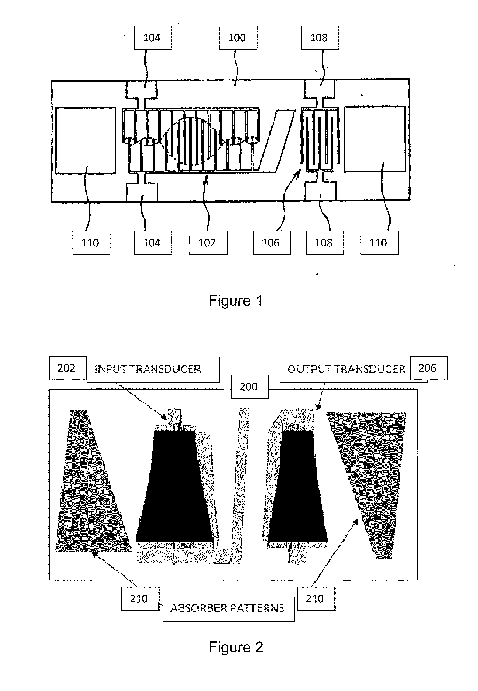
[0027]A typical SAW filter device configuration is shown in FIG. 1, including a SAW substrate 100, an input IDT transducer 102 for generating SAWs in response to an electronic input signal that is applied to metal pads 102, an output IDT transducer 106 for converting SAWs back to an electronic signal that is available at metal pads 108, and acoustic absorber material 110 that is placed between each IDT and the substrate edge. Said absorber material is effective to suppress spurious response signals that would arise from reflections from edges of the SAW substrate 100 if said absorber material were not present. It is evident from this FIG. 1 that the absorber material requires a significant amount of substrate area.

[0028]FIG. 2 shows a second typical SAW filter device for which pattern absorber is utilized. The device is comprised of a SAW substrate 200, an input IDT transducer 202, and patterned acoustic absorber 210 as is taught by R. E. Chang, et al, as referenced earlier. It is e...


PUM


Abstract

The present invention is directed to using the uniquely high reflectivity that occurs at high angles of incidence at a boundary between two SAW propagation regions for which the incident wave region has a lower SAW phase velocity. In optical systems, this region is known as the region of total internal reflection. Use of total internal reflection for SAW devices is not well known because it usually only occurs over a narrow range of angles and which are high incidence angles.

Description

CROSS REFERENCE TO RELATED APPLICATIONS[0001]This application claims the benefit of, and incorporates by reference, U.S. Patent Application Ser. No. 61 / 209,393, filed 6 Mar. 2009.[0002]This application claims the benefit of, and incorporates by reference, U.S. Patent Application Ser. No. 61 / 209,438, filed 6 Mar. 2009.[0003]This application claims the benefit of, and incorporates by reference, U.S. Patent Application Ser. No. 61 / 311,309, filed 6 Mar. 2010.FIELD OF THE INVENTION[0004]The present invention relates to surface acoustic wave (SAW) devices and, in particular, to the use of patterned structures on the SAW device substrate surface to divert the direction of SAW energy propagation and is based on the high reflectivity that occurs at high angles of incidence at a boundary between two SAW propagation regions for which the incident wave region has a lower SAW phase velocity. An important application of such diverters is to suppress various types of spurious signals that often di...

Claims


Application Information

Patent Timeline
IPC IPC(8): H03H9/25
CPCG06K19/0675G06K19/0672
Inventor HARTMANN, CLINTON S.
Owner RF SAW INC
Why Eureka
Try Eureka