

Drive unit, lens barrel, and camera
a technology of drive unit and lens barrel, which is applied in the direction of piezoelectric/electrostrictive device details, printers, camera focusing arrangement, etc., can solve the problems of low driving force not being properly output, and high power consumption for low driving force, so as to achieve the effect of reducing power consumption
- Summary
- Abstract
- Description
- Claims
- Application Information
AI Technical Summary
Benefits of technology
Problems solved by technology
Method used
Image

Examples
first embodiment
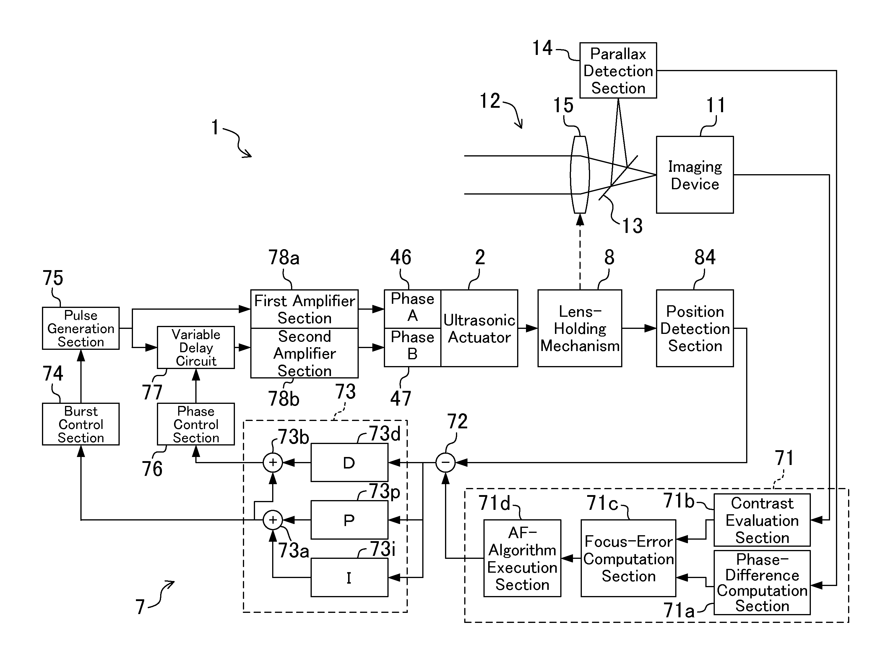
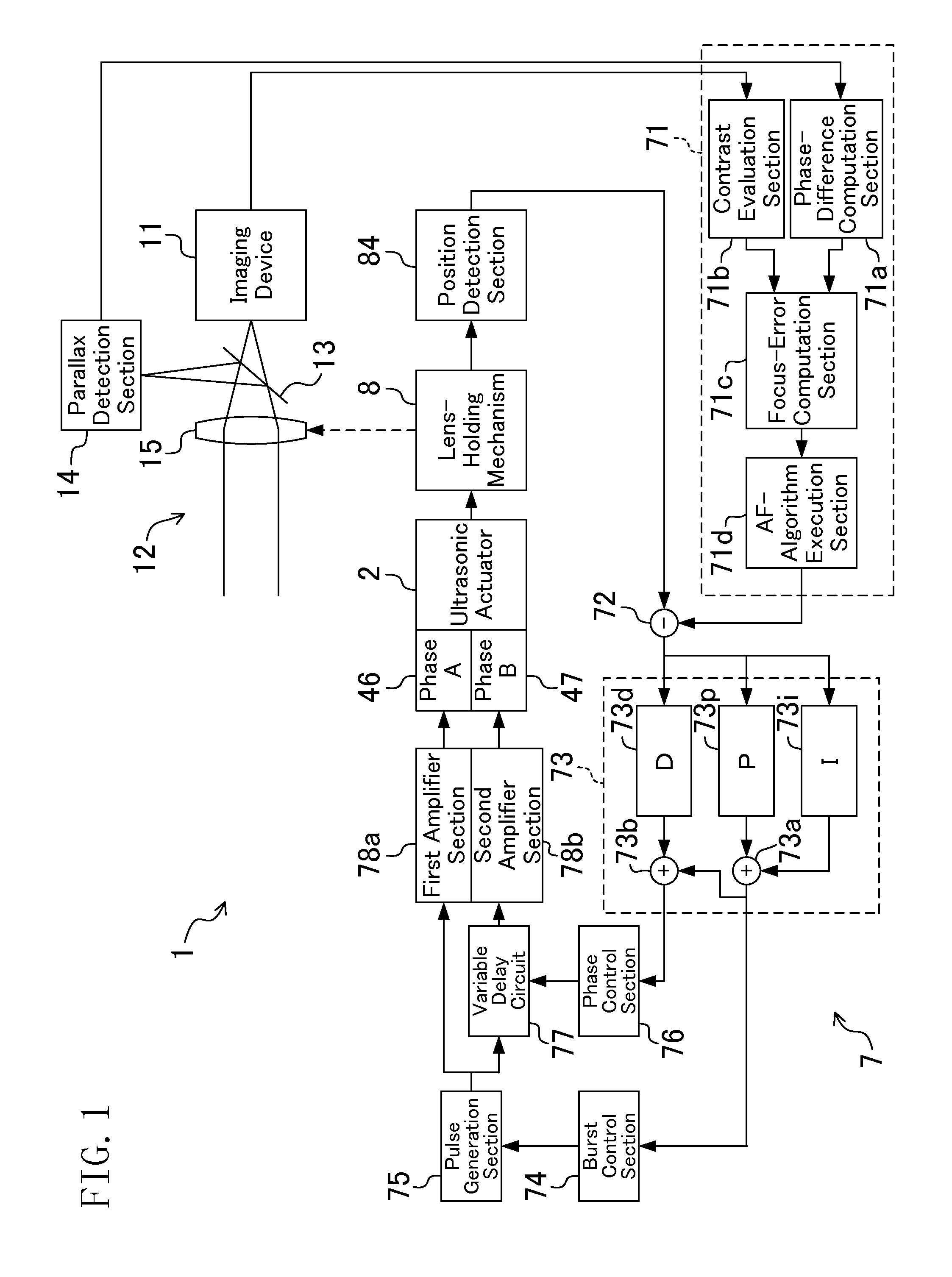
[0052]A camera system 1 which includes a drive unit in accordance with the first embodiment will now be described with reference to FIG. 1. FIG. 1 is a block diagram illustrating a configuration of a camera.
[0053]The camera system 1 includes an imaging device 11, an imaging optical system 12, which forms an object image on the imaging device 11, a reflection mirror 13 provided on an optical axis between the imaging device 11 and the imaging optical system 12, a parallax detection section 14, which receives light directed by the reflection mirror 13 and detects a parallax, and a control section 7, which controls a focusing-lens drive section 16 (described later) provided in the imaging optical system 12.
[0054]The imaging device 11 is formed of a CCD (Charge Coupled Device) or a CMOS (Complementary Metal Oxide Semiconductor), and converts an object image formed on an imaging plane to electric signals by photoelectric conversion.
[0055]The imaging optical system 12 includes a lens group...
second embodiment
[0199]Next, the second embodiment will be described.
[0200]The second embodiment is different in the method of wave-number control from the first embodiment. Thus, the same reference numerals as those of the first embodiment are used to represent equivalent elements, and the explanation thereof will be omitted.
[0201]In the second embodiment, the burst control section 74 has a map defining a relationship between the value of the monitoring parameter and the number of pulses. The burst control section 74 determines the number of pulses based on the monitoring parameter input and the map, and outputs an output signal depending on the number of pulses to the pulse generation section 75.
[0202]More specifically, as shown in FIG. 21, the map has a plurality of regions each associated with a value of the monitoring parameter, and the number of pulses is assigned to each region such that the number of pulses increases as the value of the monitoring parameter increases. For example, the burst ...
third embodiment
[0227]Next, a drive unit according to the third embodiment will be described with reference to FIGS. 26 and 27A-27B. FIG. 26 is a perspective view of a part of a lens mechanism 300 of a camera, and FIGS. 27A and 27B are schematic side views of an ultrasonic actuator 302.
[0228]The third embodiment is different in the configuration of the ultrasonic actuator 302 from the first embodiment. Thus, the same reference numerals as those of the first embodiment are used to represent equivalent elements, and the explanation thereof will be omitted.
[0229]The lens mechanism 300 includes a lens frame 310, a lens 311 held by the lens frame 310, and an ultrasonic actuator 302 attached to an attachment section 312 of the lens frame 310. The lens frame 310 is driven by the ultrasonic actuator 302 along the optical axis.
[0230]The ultrasonic actuator 302 includes an actuator body 304, which generates vibration, an anchor weight 305 attached to one end of the actuator body 304, and a drive shaft 349 at...
PUM
 Abstract
Description
Claims
Application Information