Shank drill

a technology of shank and cutter, which is applied in the field of shank cutter, can solve the problems of low cutting pressure and power consumption of the machine, the tool can produce a high cutting depth and cutting width, and the shank cutter is generally not suitable for the production of uniform surfaces, etc., and achieves high material removal rate, high tool life travel, and good surface quality.

Inactive Publication Date: 2010-09-09
GUEHRING JOERG
View PDF9 Cites 40 Cited by
  • Summary
  • Abstract
  • Description
  • Claims
  • Application Information

AI Technical Summary

Benefits of technology

[0007]The invention is therefore based on the object of developing a shank cutter of the type described at the start, in particular according to the preamble of patent claim 1 in such a manner that it is in particular suit

Problems solved by technology

The roughing cutter is however generally not suitable for the production of a uniform surface with a high surface quality.
Also, the cutting pressure and the power consumption of the machine are lower when working with such roughing cutters, and the tool can produce a high cutting depth and cutting width.
If such finishing tools are however used with greater cutting depths or

Method used


Image

  • Shank drill
  • Shank drill
  • Shank drill

Examples


Embodiment Construction

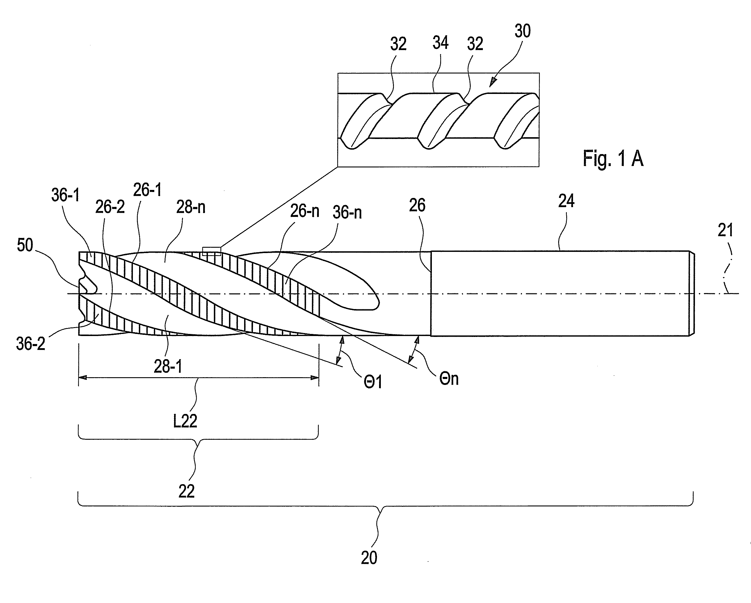
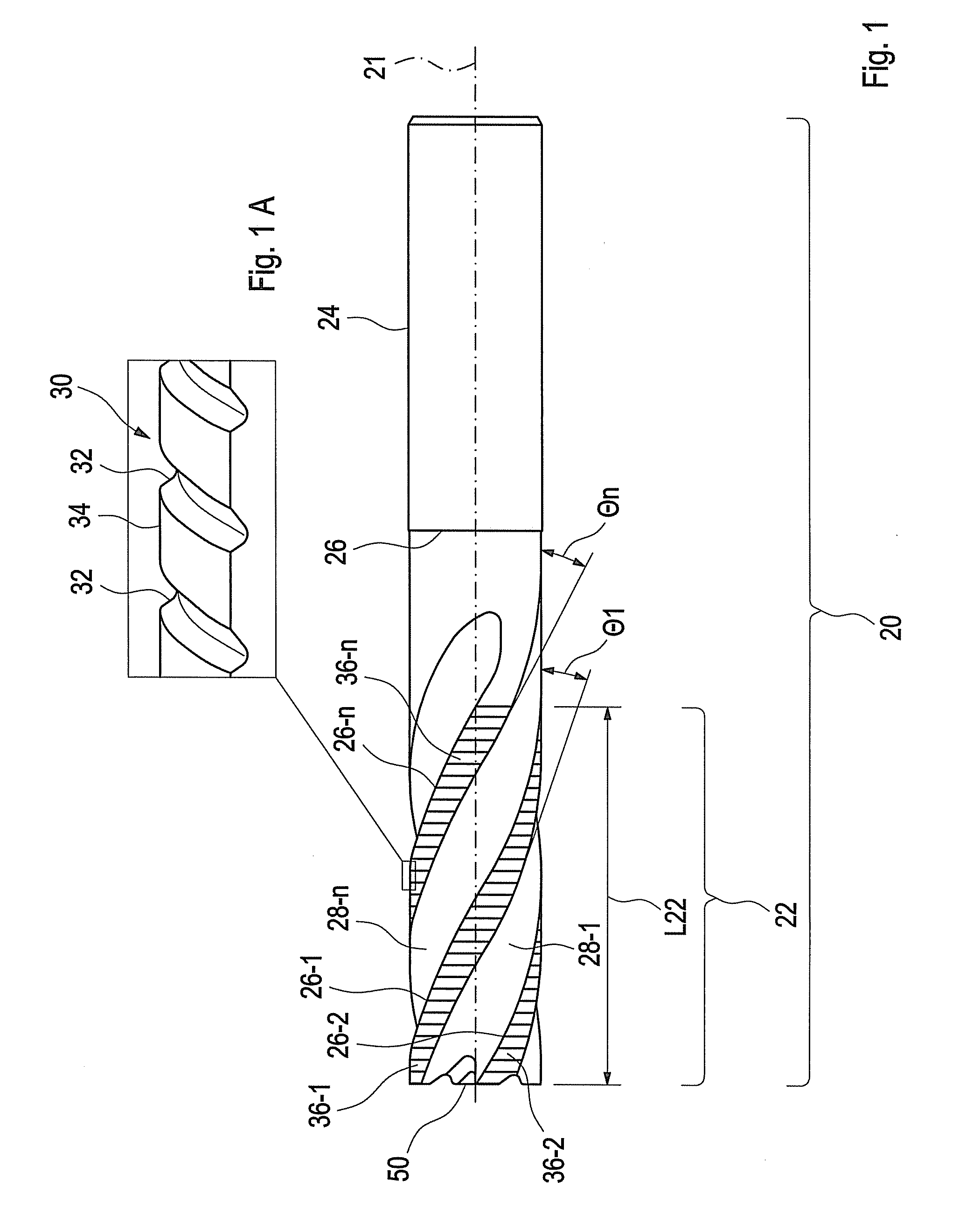
[0035]In FIG. 1, a shank cutter is referred to with the reference symbol 20 and has a cutting section 22 and a clamping shank 24. The cutter axis is referred to with 21. In the example shown, both the cutting section and the clamping shank have a cylindrical configuration. The cutting section can however equally have a different envelope, for example an envelope in the shape of a cone surface.

[0036]The line 26 indicates that the shank cutter has what is known as a neck countersink, that is, the outer diameter of the clamping shank 24 is slightly bigger than the nominal diameter of the cutting section 22.

[0037]The cutting section 22 has a plurality of circumferential cutting edges 26-1 to 26-n, which run in a helical manner and between which flutes 28-1 to 28-n are formed. In this shank cutter the circumferential cutting edges are the main cutting edges. At the end face is formed a number of auxiliary cutting edges which corresponds to the number of circumferential cutting edges in a...


PUM

PropertyMeasurementUnit
Angleaaaaaaaaaa
Angleaaaaaaaaaa
Angleaaaaaaaaaa

Abstract

A shank cutter has plural circumferential cutting edges which run in a helical manner in the region of its cutting section and of which at least one critical number are equipped in each case with a preferably essentially flattened roughing profile with chip-separating grooves with rounded bases, so that the chip-separating grooves of cutter ridges which are adjacent in the circumferential direction are axially offset relative to each other. To create a tool which provides long service life by combined advantages of a vibration-stabilized finishing cutter and a conventional roughing cutter, at least one circumferential cutting edge has an angle of twist which differs from that of another circumferential cutting edge. In addition, the chip-separating grooves of the circumferential cuffing edges which are equipped with a roughing profile in each case merge into a preferably essentially flattened central section of the roughing profile by means of a predefined flank radius.

Description

FIELD OF THE INVENTION[0001]The invention relates to a shank cutter according to the preamble of patent claim 1.BACKGROUND OF THE INVENTION[0002]Such cutters have as a common feature a shank as the chucking part, which is inserted into the tool holder. Such cutters are used for example as slotting cutters or die-sinking cutters with a flat or round end. Such cutters are furthermore characterised in that they have a plurality of circumferential cutting edges in the region of their cutting section on the cutter ridges which are separated from each other by flutes, which cutting edges run in a helical manner and are in each case configured with a roughing profile in such a manner that the circumferential cutting edges are given chip-separating grooves, with the chip-separating grooves of cutter ridges which are adjacent in the circumferential direction being axially offset with respect to each other.[0003]Such roughing profiles are standardised in “round” and “flat” versions for exampl...

Claims


Application Information

Patent Timeline
IPC IPC(8): B23C5/10
CPCB23C5/003B23C5/10B23C2210/0485B23C2210/0492B23C2210/086Y10T407/1948B23C2210/282B23C2210/486B23C2220/60B23C2250/16Y10T407/1958B23C2210/088Y10T409/303752
Inventor STRASMANN, MARTIN
Owner GUEHRING JOERG
Why Eureka
Try Eureka