
Systems and methods for dynamic spinal stabilization

a dynamic spinal and stabilization technology, applied in the field of medical devices, can solve the problems of pedicle screw loosening affecting the normal physiologic motion, etc., and achieve the effect of facilitating dynamic stabilization and facilitating dynamic stabilization

Inactive Publication Date: 2010-09-09
NUVASIVE
View PDF2 Cites 78 Cited by
  • Summary
  • Abstract
  • Description
  • Claims
  • Application Information

AI Technical Summary

Benefits of technology

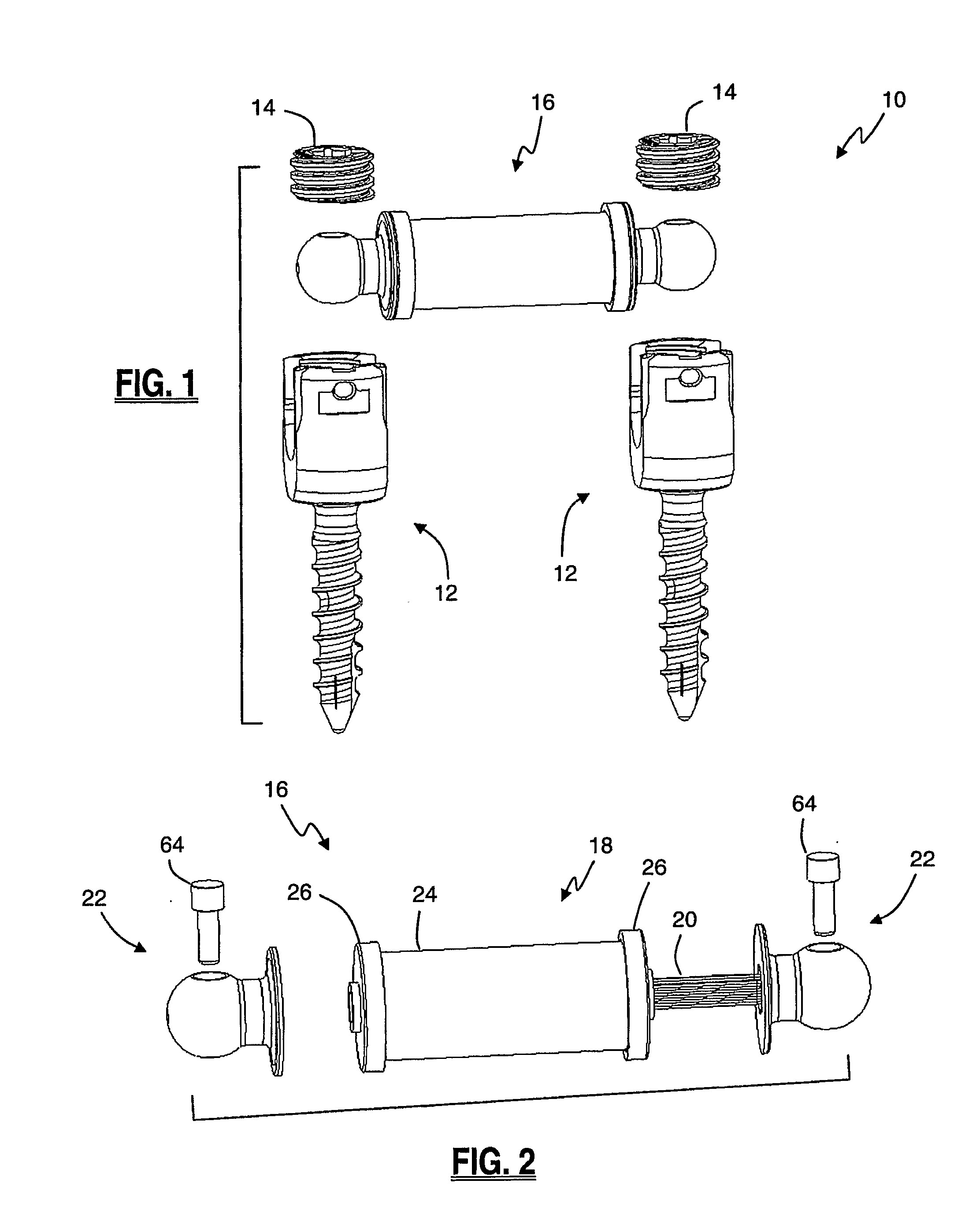
[0014]A method of assembling the components of the dynamic rod may be performed, by way of example only, as follows. First, one end of the tension cord is attached to a coupler assembly with a pin. The bumper assembly is then inserted over the free end of the tension cord. Next, a second coupler assembly is attached to the tension cord with another pin. To tension the tension cord, the coupler assemblies are rotated in opposite directions relative to each other. This imparts a series of twists to the tension cord. The twisting of the cord shortens the length and adds tension to the tension cord. As the tension cord length decreases, the coupler assemblies are drawn together with the bumper assembly. Once the desired tension level is reached, twisting is halted, the tension level is verified (optional), and the components are welded together (also optional). The assembled dynamic rod may be packaged, sterilized, and delivered to the operating room ready for implantation such that the surgeon need only retrieve the dynamic rod from the packaging and attach it to the pedicle screws anchored in the patient's spine.
[0017]According to an alternate embodiment of the present invention, a hybrid rod may be provided. The hybrid rod facilitates dynamic stabilization at one level of the spine and fusion or rigid fixation at another level. The rod differs from the dynamic rod previously described in that a rigid rod portion extends from one end of the bumper assembly.

Problems solved by technology

These normal physiologic motions may be impeded and / or pain generating when any of a number of conditions exists, including but not limited to disc degeneration, trauma, and deformity (e.g. scoliosis).
Although generally effective, fusion procedures do have a number of potential drawbacks.
One drawback stems from the fact the pedicle screws are introduced directly into the vertebra.
This results in significant forces being loaded on the vertebra, which may ultimately result in the loosening of the pedicle screw.
Another potential drawback to fusion is that while fusion generally results in a strengthened portion of the spine at the fusion level, it also results in increased loads being placed on adjacent spinal levels.
This in turn may result in increased degeneration, hyper-mobility, and collapse of spinal motion segments adjacent to the fused segment, thereby reducing or even eliminating the ability of the adjacent spinal joints to support normal physiologic motions.
A still further drawback stems from fusion itself, in that fusion limits the mobility of the patient and yet may fail to provide adequate pain relief for the patient.
Although generally effective at stabilizing a spinal segment, the Dynesys® system suffers from several significant drawbacks.
One drawback is the need to intra-operatively assemble the dynamic aspects of the system, namely, the polyurethane tubing and the polyethylene cord.
This need to intra-operatively tailor the polyurethane tubing and polyethylene cord consumes precious operative time, which translates into higher costs to the hospital, and increases the risk to the patient due to the longer surgical time.
Another significant drawback to the Dynesys system is the “side-loading” nature of the pedicle screws and the need to thread the polyethylene cord through the side-loading housings and tension the cord intra-operatively during the assembly process.
The need to thread the polyethylene cord through the side-loading housing and through the polyurethane tubing, as will be appreciated, increases the difficulty and “fiddle factor” of the system and hence increases the amount of time required to assemble the system.
The need to tension the polyethylene cord intra-operatively not only adds time to the procedure, but also introduces variability into the surgery, as different surgeons may choose to tension the device more or less robustly than others.
This may affect the outcome of each particular surgery, making some better and some worse, based on the variability in assembly.
This cuts against the general surgical goal to provide “safe and reproducible” surgical outcomes.

Method used


Image

  • Systems and methods for dynamic spinal stabilization
  • Systems and methods for dynamic spinal stabilization
  • Systems and methods for dynamic spinal stabilization

Examples


Embodiment Construction

[0051]Illustrative embodiments of the invention are described below. In the interest of clarity, not all features of an actual implementation are described in this specification. It will of course be appreciated that in the development of any such actual embodiment, numerous implementation-specific decisions must be made to achieve the developers' specific goals, such as compliance with system-related and business-related constraints, which will vary from one implementation to another. Moreover, it will be appreciated that such a development effort might be complex and time-consuming, but would nevertheless be a routine undertaking for those of ordinary skill in the art having the benefit of this disclosure. The dynamic stabilization systems disclosed herein boast a variety of inventive features and components that warrant patent protection, both individually and in combination.

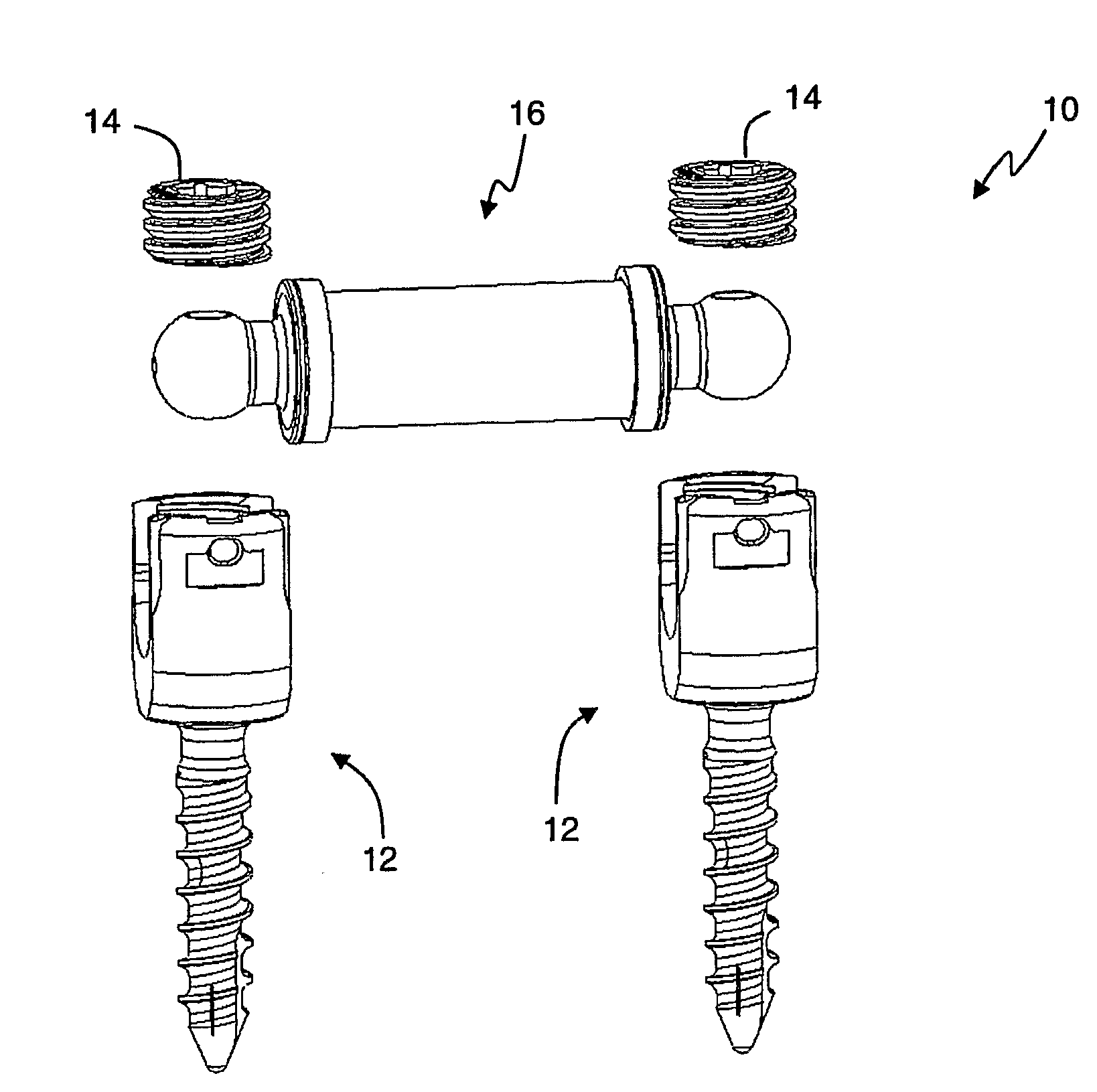
[0052]A dynamic stabilization system 10, according to one embodiment of the present invention, is illustra...


PUM


Abstract

A dynamic stabilization system including a dynamic rod with a first and second coupler assemblies, a pre-tensioned central cord and a flexible bumper, which are coupled to the bony structures of the spine by way of pedicle screws for use in spinal fixation surgery.

Description

CROSS-REFERENCE TO RELATED APPLICATIONS[0001]This is an International Patent Application claiming the benefit of priority under 35 U.S.C. §119(e) from the commonly owned and co-pending U.S. Provisional Patent Application Ser. No. 60 / 833,236, entitled “System and Methods for Dynamic Stabilization” and filed on Jul. 24, 2006, the entire contents of which is expressly incorporated by reference into this disclosure as if set forth in its entirety herein.BACKGROUND OF THE INVENTION[0002]I. Field of the Invention[0003]The present invention relates to medical devices generally aimed at spinal surgery and, more particularly, to systems and methods for performing dynamic spinal stabilization.[0004]II. Discussion of the Prior Art[0005]The human spine is comprised of a plurality of components (e.g. vertebral bodies, intervertebral discs, posterior bony structures) which collectively protect the spinal cord and enable the normal physiologic motions of flexion (bending forward), extension (bendi...

Claims


Application Information

Patent Timeline
IPC IPC(8): A61B17/70
CPCA61B17/7005A61B17/7037A61B17/7031A61B17/7008
Inventor ARNOLD, BENJAMINANAND, NEELTAYLOR, WILLIAMMUELLER, RICHDASSO, ERICCORNWALL, G. BRYANCOPP, MATTHEW
Owner NUVASIVE
Learn More