Energy Extraction Method and Apparatus

a technology of energy extraction and energy, applied in the direction of propulsive elements, auxiliaries, water-acting propulsive elements, etc., can solve the problems of low efficiency of wave energy conversion in this device, visual pollution, and public opposition to onshore devices, so as to reduce the load of shook on energy extraction devices, increase service life and cost effectiveness, and increase energy extraction

Inactive Publication Date: 2010-09-16
SEADOV
View PDF6 Cites 8 Cited by
  • Summary
  • Abstract
  • Description
  • Claims
  • Application Information

AI Technical Summary

Benefits of technology

[0008]The present invention aims to overcome or alleviate one or more of the above disadvantages by providing an energy extraction method and apparatus which allow for an increase in energy extraction from naturally occurring phenomena by a synergistic interaction between

Problems solved by technology

OWC devices have been constructed on exposed rocky coastlines, however these onshore devices may be opposed by the public on the grounds of visual pollution.
The efficiency of conversion of wave energy in this device however was found to be low because the floating body was too small and light for the prevailing wave period and tended to move up and down with the swell, cancelling out most of the relative movement between the body and the surrounding water.
Another device, the Osprey, was not based on a ship hull and was not able to weather a storm when it was being towed into position.
A third device, the Swedish Floating Wave Power Vessel, is a large, expensive purpose-built structure which only captures energy from a small length of wave front, so that the capital cost per unit of rated output is high.
A further problem with known OWC devices is that the fixed vertical wall of the chamber facing the oncoming swells shuts out much of the available energy because the water moves in an orbital motion, with the water at the wave crest advancing in the direction of motion of the wave.
These wind turbines have the gearbox and generator assembly housed in a nacelle at the top of the tower, and in large, multi-megawatt machines t

Method used


Image

  • Energy Extraction Method and Apparatus
  • Energy Extraction Method and Apparatus
  • Energy Extraction Method and Apparatus

Examples


Embodiment Construction

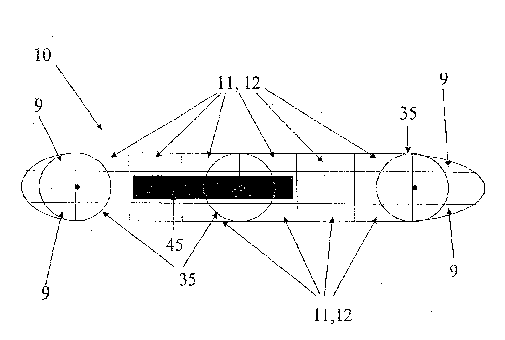
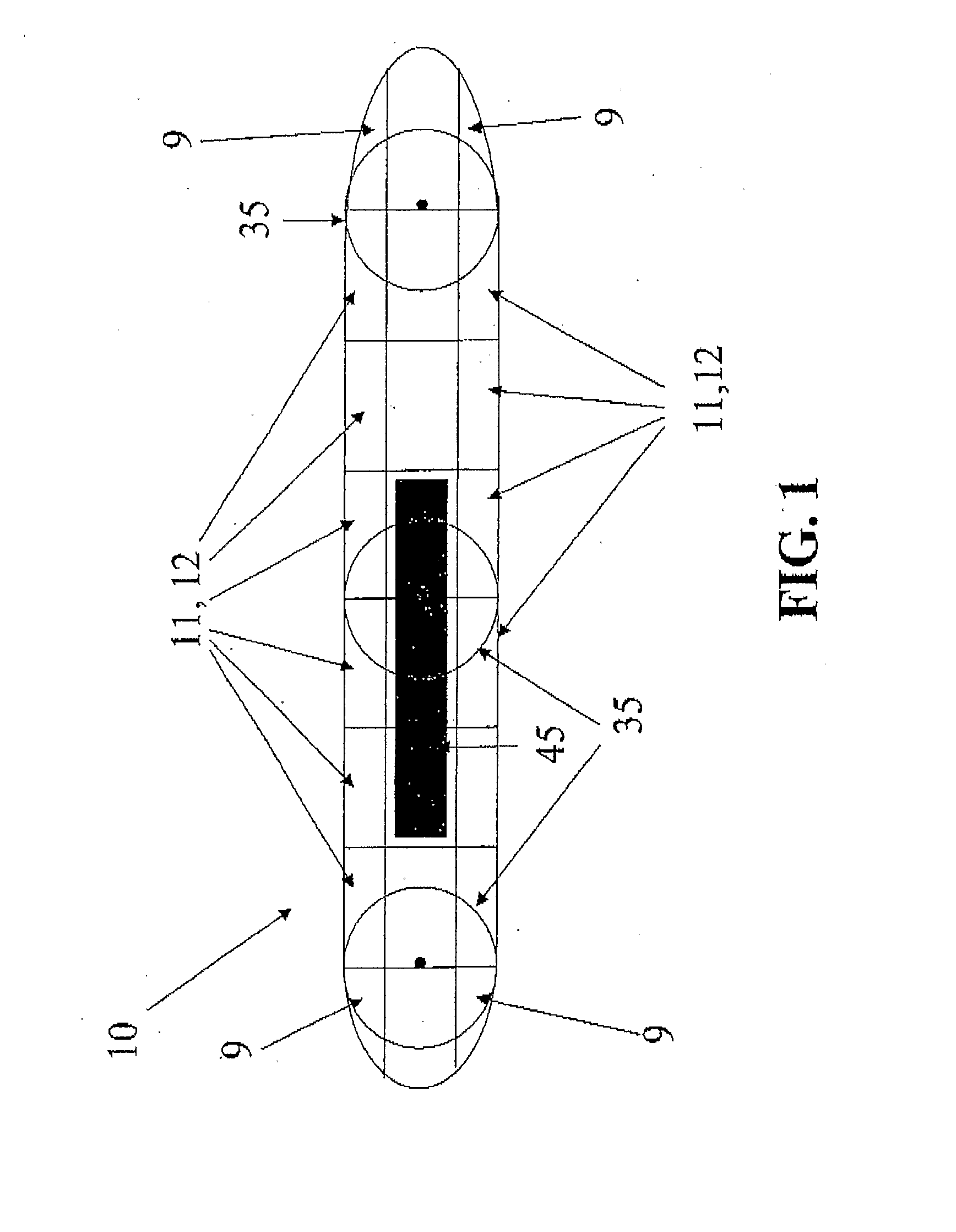
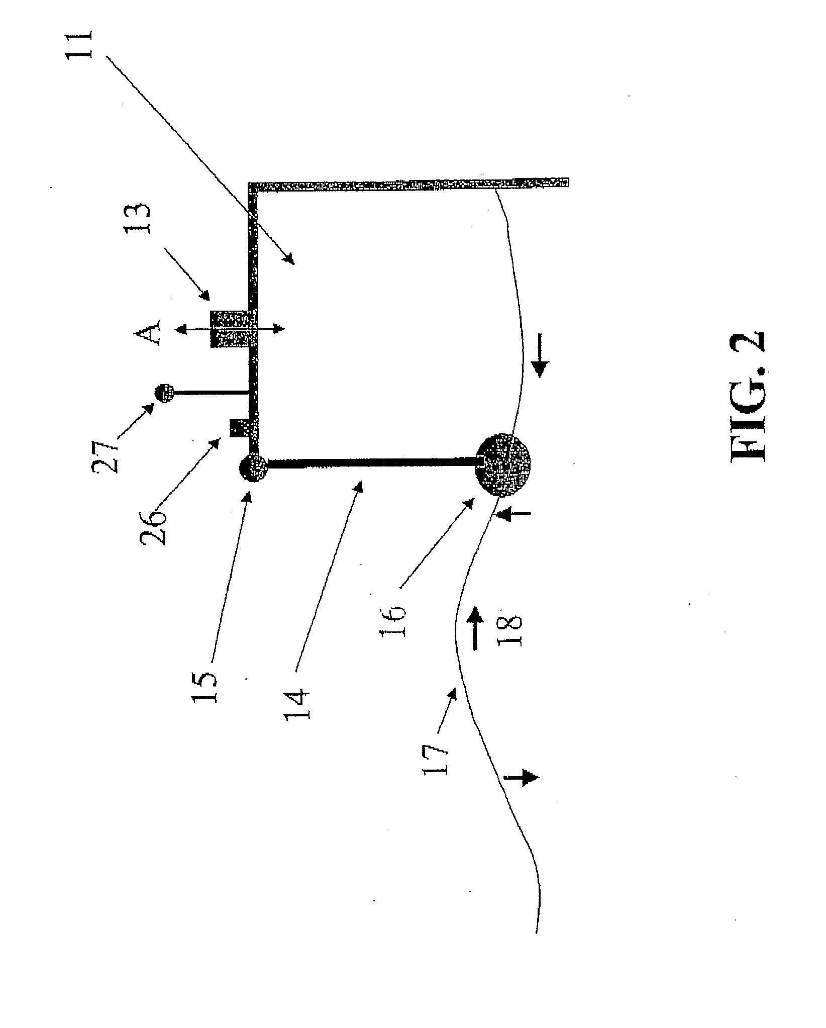
[0054]FIG. 1 illustrates a typical hull 10 of a vessel such as a large oil tanker hull which houses or carries the energy extraction means according to the invention. Arranged along one or both sides of the hull 10 are a plurality of air chambers 11 of oscillating water column (OWC) wave energy conversion devices 12, the chambers 11 being open at their lower ends through the hull and housing or supporting at their upper end bi-directional air turbines 13 (see FIG. 2) which communicate with the interiors of the chambers 11. The hull 10, because of its large mass and moment of inertia about both longitudinal and transverse axes, stays in a substantially fixed position relative to short period wave motion, but preferably heaves, rolls and pitches out of phase with the wave motion and thus maximises upward and downward movement of the water in waves relative to the chamber 11 which will compress the air within the chamber 11 and thereafter allow for expansion of air within the chamber 1...


PUM


Abstract

A method and apparatus for extracting energy from wind and wave motion using a common floating platform comprising a ship hull (10) which is moored in an offshore location and which supports wind turbines (27) for extracting energy from wind and wave energy extraction devices (12) positioned at least at one side of the hull (10) for extracting energy from wave motion relative to the hull (10). The method and apparatus may also use water current energy extraction devices. The hull (10) may also support a desalination plant (45) which uses the energy generated from the wind, wave and water current energy extraction devices.

Description

TECHNICAL FIELD[0001]This invention relates to an integrated, synergistic combination of devices for extracting energy from naturally occurring phenomena including waves, wind and marine currents, including tidal flows, to generate electrical energy. The present invention in a particular aspect aims to provide a beneficial interaction between one or more wave energy conversion devices, one or more wind turbines and / or one or more marine current turbines mounted on a ship hull.BACKGROUND ART[0002]Oscillating water columns (OWCs) are well-known devices for extracting energy from waves, and comprise a chamber having a bottom which is open and underwater and with an opening at the top, above water, the chamber housing or communicating with one or two air turbines with or without non-return valves, arranged in such a way that a turbine is turned so as to produce power regardless of whether air is flowing into or out of the chamber consequent upon wave motion. A preferred method is to use...

Claims


Application Information

Patent Timeline
IPC IPC(8): F03B13/14F03D9/00
CPCB63J1/00B63J3/04F03B13/142F03B13/24F03B17/063Y02E10/72F05B2220/62F05B2240/931Y02E10/28Y02E10/32Y02E10/38F03D9/008F03D9/25F03D13/25F03D15/10Y02E10/30Y02E10/727Y02A20/141Y02A20/144Y02E10/20
Inventor GRIFFIN, PHILIP J.KIRKE, BRIAN KINLOCHPARKER, PETER DONALD
Owner SEADOV
Why Eureka
Try Eureka