Method for controlling a polyphase voltage inverter

a voltage inverter and polyphase technology, applied in the direction of dynamo-electric converter control, motor/generator/converter stopper, polyphase induction motor starter, etc., can solve the problem of large memory consumption, inability to determine the quantity of neutral to be added, and control techniques with drawbacks

Inactive Publication Date: 2010-09-16
VALEO EQUIP ELECTRIC MOTEUR
View PDF7 Cites 4 Cited by
  • Summary
  • Abstract
  • Description
  • Claims
  • Application Information

AI Technical Summary

Benefits of technology

[0016]The quantity of neutral to be added to the modulants stems either from the comparison of the absolute values of the currents or from the position of the instruction voltage vector. These novel control...

Problems solved by technology

Such control techniques have drawbacks.
This is because it is not possible to determine the quantity of neutral to be added to the modulants when the system is not in permanent mode.
In addition, in permanent mode, this quantity of neutral is either calculated in line, which requires a fairly long calculation time, ...

Method used


Image

  • Method for controlling a polyphase voltage inverter
  • Method for controlling a polyphase voltage inverter
  • Method for controlling a polyphase voltage inverter

Examples


first embodiment

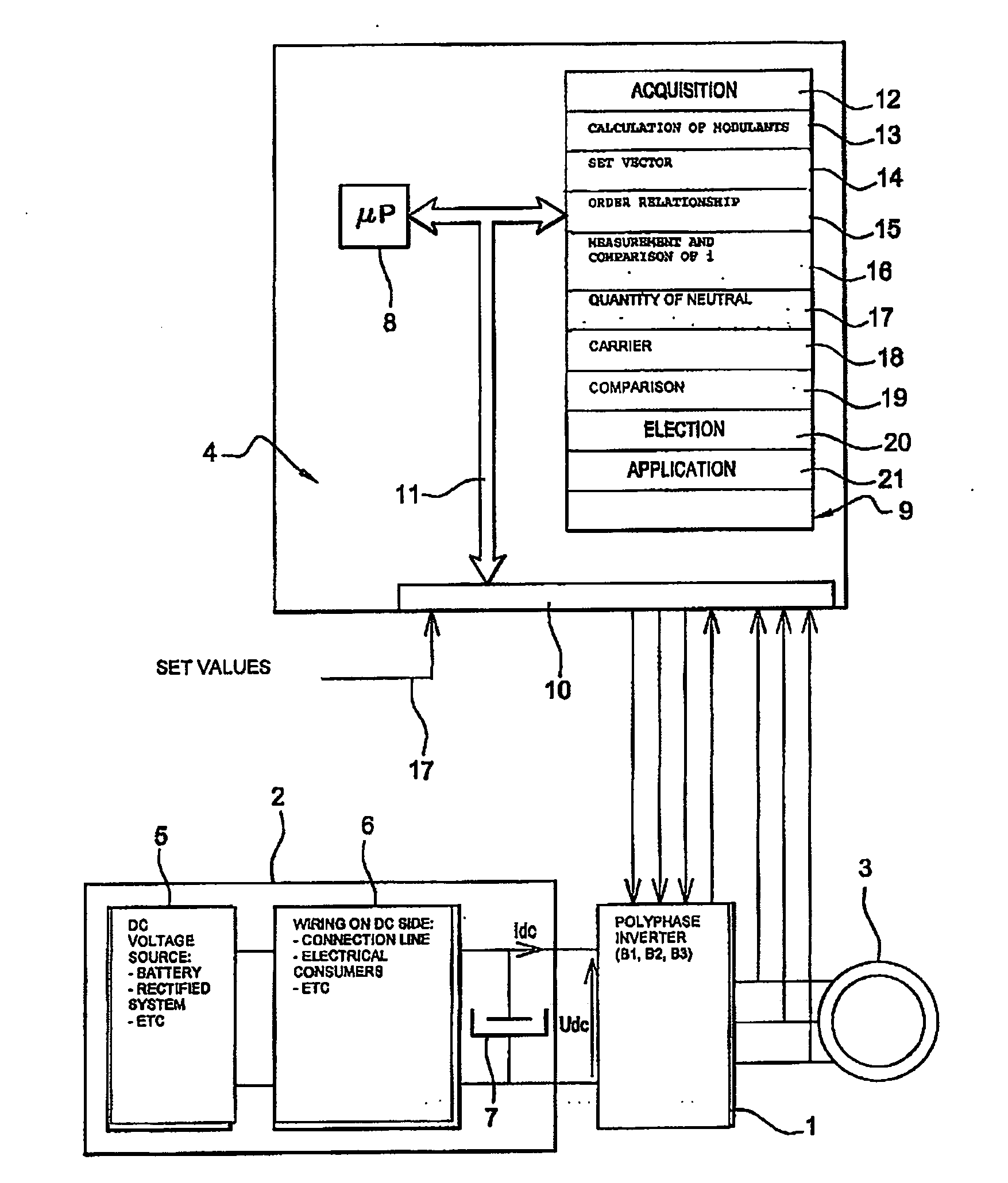
[0121]In a first embodiment, the bridge arm to be inhibited with respect to the phase currents is determined. In this case, in order to determine the bridge arm to be inhibited, the control logic 4 applies steps 40 to 45. Inhibiting a bridge arm means keeping the said bridge arm in a given state. In other words, the states of the switches of the said bridge arm remain unchanged. There is no switching of the arm.

[0122]At step 40, the control logic determines the bridge arm to be inhibited with respect to the current vector {right arrow over (i)}. The inhibiting of a bridge arm will make it possible to reduce the switching losses in the switches.

[0123]To this end, at step 41, in a first, non-limitative variant embodiment, the control logic 4 first selects two bridge arms among the three, able to be inhibited according to an order relationship between the three modulants mod1, mod2, mod3 of the three bridge arms, this order relationship being, in a non-limitative example, a comparison....

second embodiment

[0143]In a second embodiment, the bridge arm to be inhibited is determined with respect to the set voltage vector {right arrow over (V*)} and more particularly the sectorial position of the set voltage vector in one of the angular sectors SA of the stator reference frame. In this case, to determine the bridge arm to be inhibited, the control logic 4 applies steps 50 to 55.

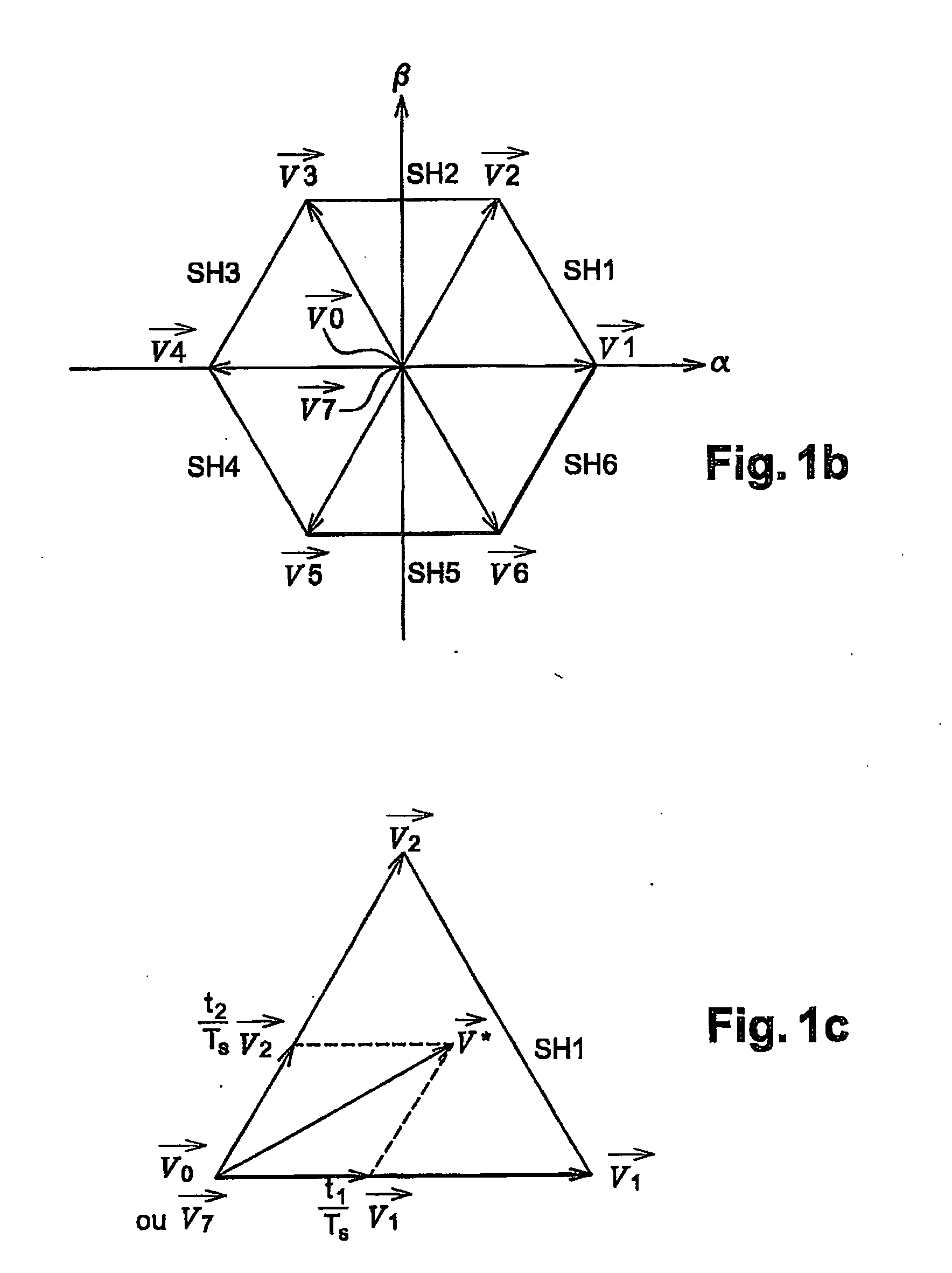
[0144]In this case, the stator reference frame is subdivided into angular sectors SA illustrated in FIG. 3. Each angular sector has its vertex at the centre of the stator reference frame and forms an angle of 60°. Each of the active control vectors cuts each of the angular sectors into two equal parts. The stator reference frame comprises six angular sectors SA. The first angular sector SA1 is cut into two equal parts by the control vector {right arrow over (V1)} and so on up to the sixth angular sector SA6, which is cut by the control vector {right arrow over (V6)}.

[0145]At step 50, the control logic 4 determines ...


PUM


Abstract

A method for driving a power bridge (1) which is used for controlling a multiphase electric load (3), is connectable to said electric load (3) through several arms and is drivable by switching functions determining control vectors for controlling the load, wherein said control vectors are subdivided into the free wheel control vectors and active control vectors. The inventive method is characterised in that it comprises the use of a switching function production method which produced a reduced number of switching function combinations corresponding to the free wheel control vectors for producing a sequence of the control vectors.

Description

FIELD OF THE INVENTION[0001]The invention concerns a method of controlling a power bridge intended to control an electrical load comprising several phases, the power bridge being intended to be connected to the electrical load via several arms, at least one per phase, and being intended to be controlled by switching functions, the said switching functions determining control vectors for controlling the load, the said control vectors being subdivided into freewheeling control vectors and active control vectors.[0002]The present invention finds particularly advantageous, but not exclusive, applications in the fields of the automobile sector, the aeronautic sector and the industrial sector.[0003]One aim of the invention is to reduce losses in a polyphase voltage inverter.[0004]Another aim of the invention is to keep control over the polyphase load downstream of the inverter while reducing the switching losses of the inverter.[0005]It also concerns a device implementing the said method ...

Claims


Application Information

Patent Timeline
IPC IPC(8): H02P27/06H02M7/5387
CPCH02M7/53875H02P27/12H02M2007/53876H02M7/53876
Inventor HOBRAICHE, JULIENVILAIN, JEAN-PAUL
Owner VALEO EQUIP ELECTRIC MOTEUR
Why Eureka
Try Eureka