Stator structure and rotating electrical machine using the same

a technology of stator cores and rotating electrical machines, which is applied in the direction of windings, magnetic circuit rotating parts, magnetic circuit shape/form/construction, etc., can solve the problems of difficult winding of stator cores, etc., to eliminate the fear of noise and/or vibration under action, reliably fix a plurality of stator cores, and resolve magnetic instability

Inactive Publication Date: 2010-09-23
NISCA KK
View PDF4 Cites 30 Cited by
  • Summary
  • Abstract
  • Description
  • Claims
  • Application Information

AI Technical Summary

Benefits of technology

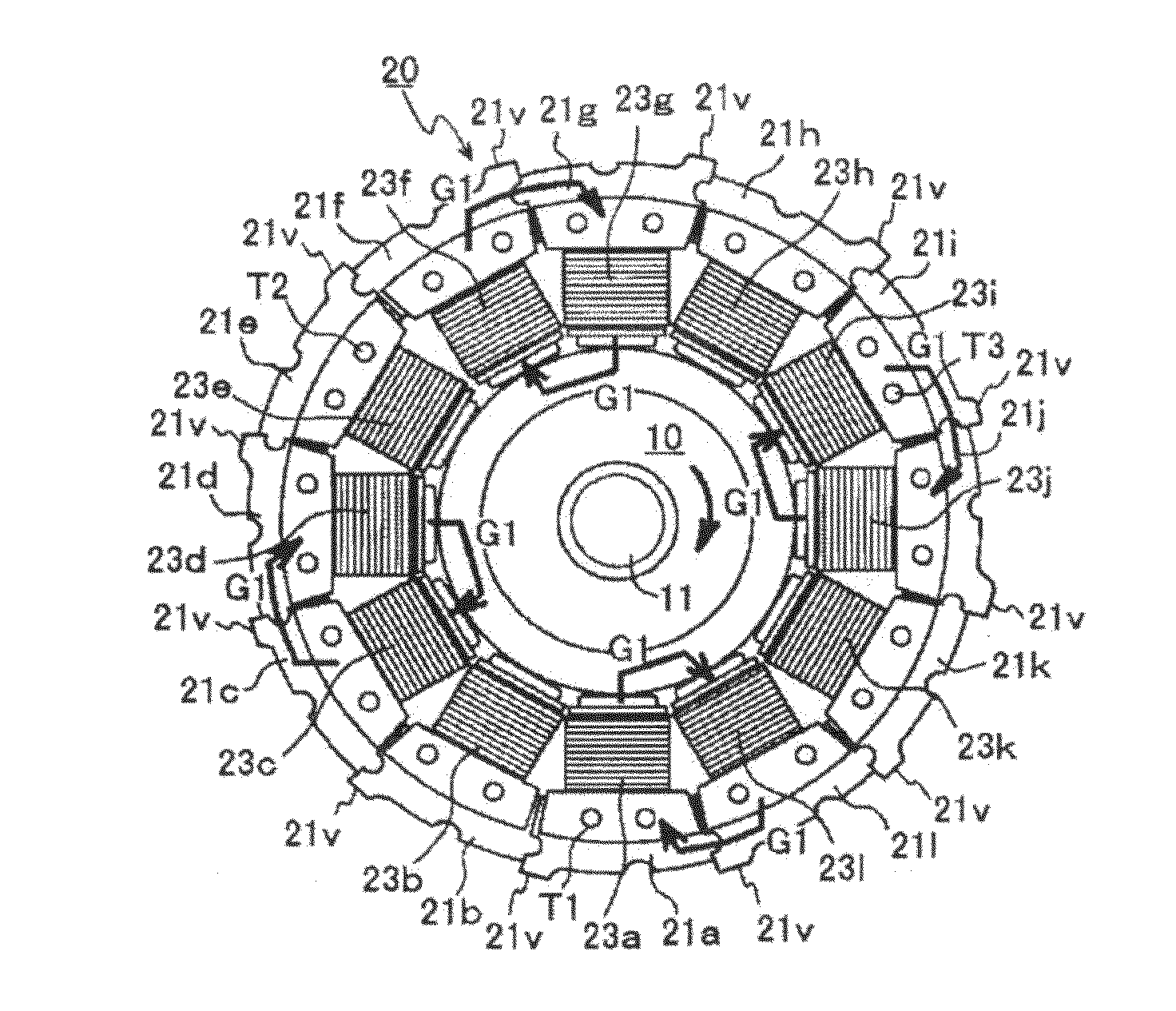
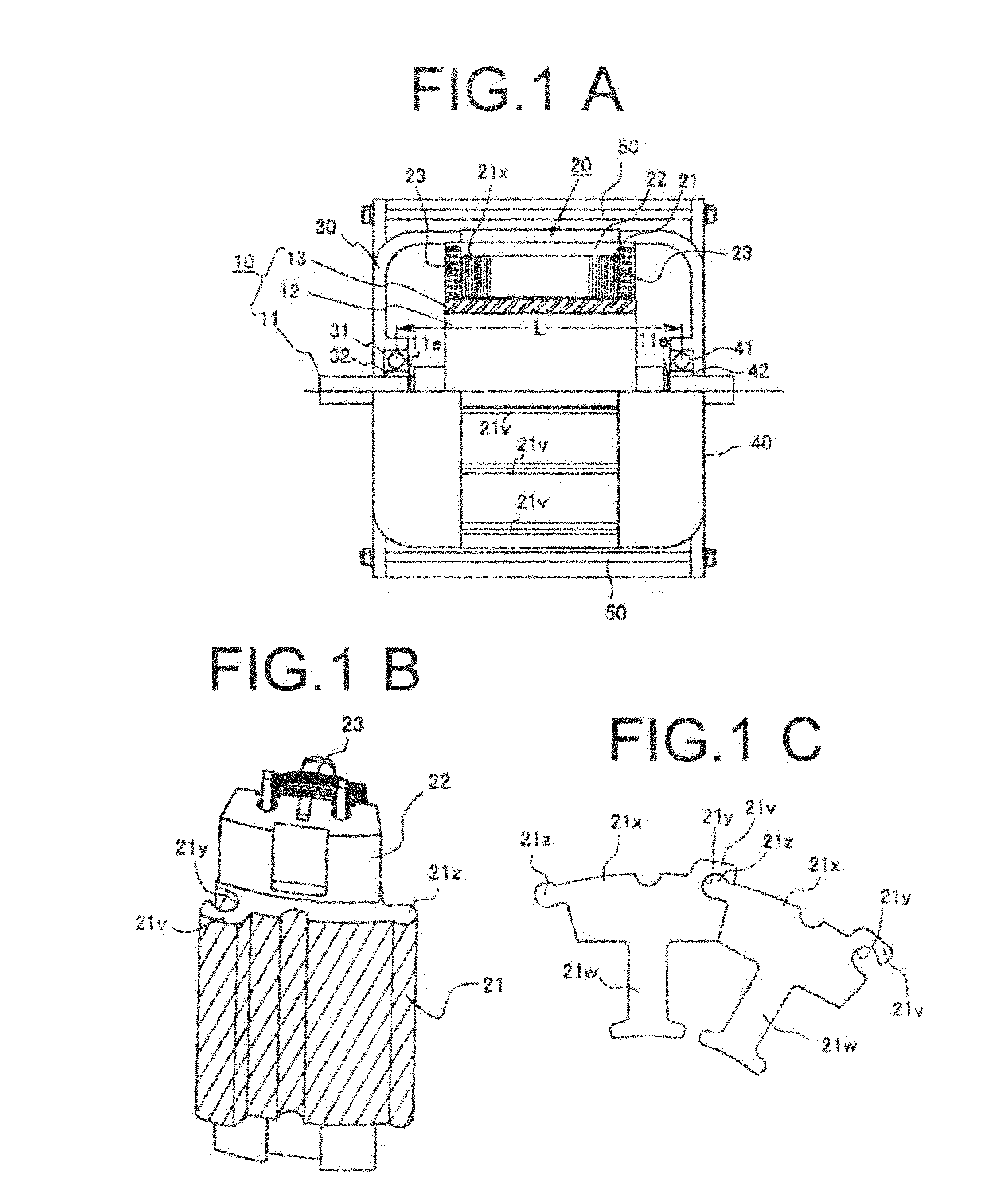
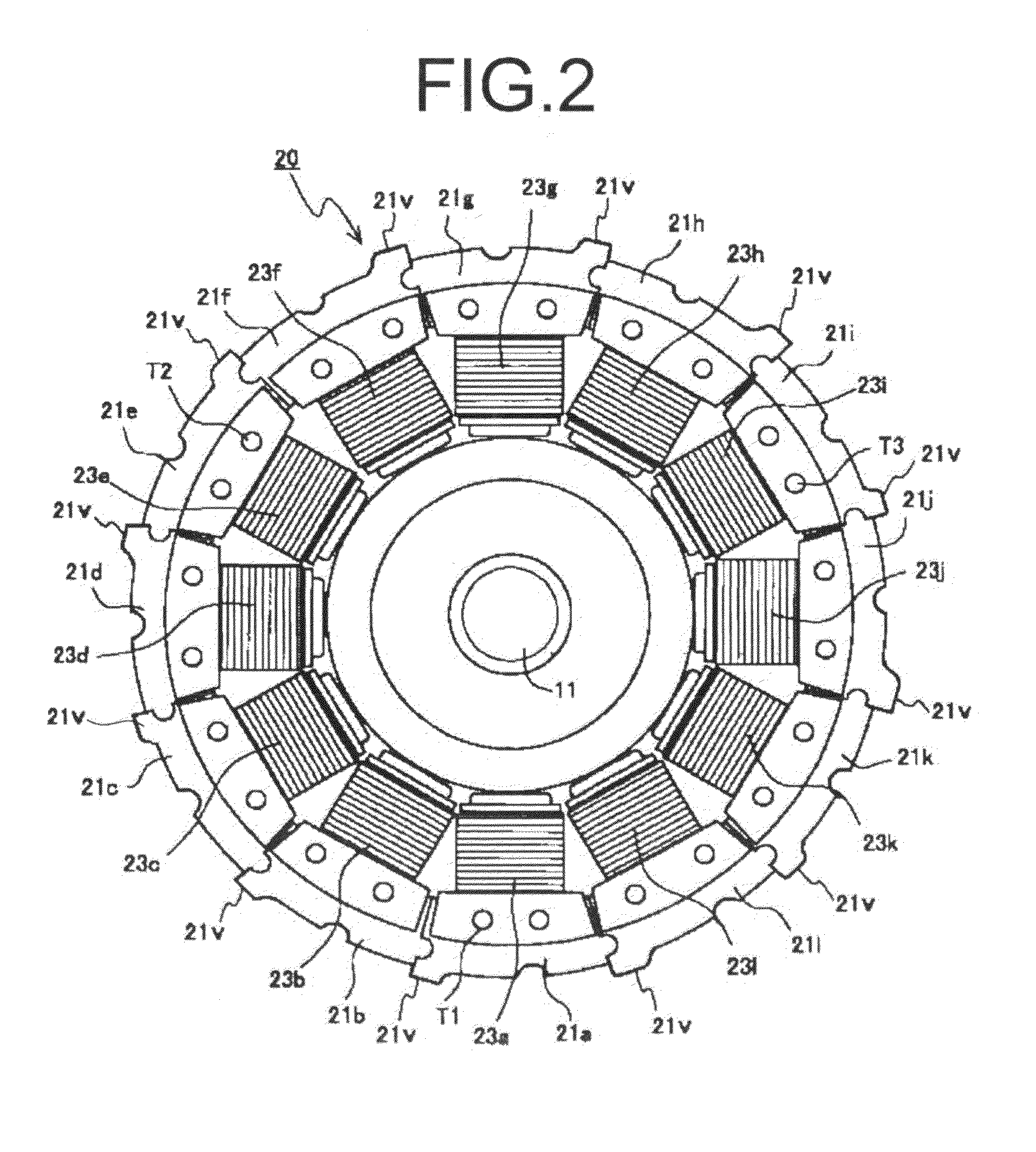
[0023]In a plurality of stator cores formed by laminating electromagnetic steel plates, their one end faces are regulated in position by the first contact surface and arranged in alignment with one another on the reference plane in the rotary shaft direction, and the other end faces are held by the second contact surface. At this point, the second contact surface deforms in accordance with the core dimension by the fastening force of the fastening member for coupling the first and second bracket members. By this means, the plurality of stator cores is aligned in their one end faces on the reference plane, and is pressed and supported in the other end faces by the deformation surface deforming corresponding to fluctuations in dimensional accuracy. Accordingly, a plurality of stator cores arranged annularly around the magnet rotor is reliably secured and supported between the first and second brackets, and each stator core does not rattle, and eliminates the fear of occurrence of noise and / or vibrations under action.
[0024]Further, in the invention, the second bracket member forming the deformation surface is made of a material softer than the stator core formed from electromagnetic steel plates, the deformation surface deforms to follow the core dimension by the fastening force of the fastening member, and it is thus possible to reliably fix a plurality of stator cores having dimensional differences without requiring specific processing.
[0025]Furthermore, the deformation surface is formed in the shape of an inclined positive-cone curbed surface, the vertex of the cone curbed surface is formed in the shape substantially in agreement with the shaft center of the rotary shaft, and it is thereby possible to arrange a plurality of stator cores in the shape of a positive cone with reference to the shaft center of the rotary shaft of the stator core. It is thus possible to bring shaft centers of the rotor and stator cores into agreement with each other.
[0026]Still furthermore, the invention is capable of providing a rotating electrical machine which is formed as a single stator core by combing a plurality of division cores, where at least one of a pair of end brackets nipping the stator core in a sandwich shape is formed of an annular magnetic material for coupling magnetically between division cores, and the division cores are magnetically connected to one another and thereby resolve magnetic instability, and which has stable rotation characteristics without fluctuations in rotation.
[0027]Moreover, as a result of coupling between division cores magnetically using the end bracket, the need is eliminated of wrapping and enclosing the division core with a yoke case, and the end faces of the division cores can be configured as an external wall of the machine. Then, by forming a cooling fin partially protruding through the outside end, heat generated inside the machine is spontaneously released with efficiency, and it is possible to reduce a heat loss and increase rotation efficiency.

Problems solved by technology

Accordingly, it is very difficult to wind the stator coil that is wound around the plurality of magnetic pole portions, and the automatic winding machine for automatically winding the coil is complicated and considerably expensive.
However, when a stator core is formed of a plurality of division cores, the magnetic reluctance is high in the junction between division cores, a magnetic circuit is hard to form, and magnetic instability thereby occurs and becomes a factor of fluctuations in rotation.
In the case of such a structure where a plurality of stator cores is coupled annularly to prepare the stator coils, and is sandwiched by a pair of brackets from the front and back of the rotary shaft, the thickness shape of each core becomes a problem.
Referring to FIG. 7, since each stator core is configured by laminating a plurality of electromagnetic steel plates, it is extremely difficult to manufacture the stator core in a uniform thickness shape.
Concurrently therewith, the magnetic forces of the magnetic teeth formed around the periphery of the rotor change, thereby resulting in a cause of fluctuations in rotation.
For example, when the rolled steel plate undergoes press die-cutting, die-cutting is performed along the rolling direction where fluctuations in material thickness are small, and its manufacturing is thus difficult and becomes a factor of high cost.

Method used


Image

  • Stator structure and rotating electrical machine using the same
  • Stator structure and rotating electrical machine using the same
  • Stator structure and rotating electrical machine using the same

Examples


embodiment 1

[Embodiment 1 of the Second Bracket]

[0059]Further, with respect to the second bracket 40, the second contact surfaces 43 are formed in the second bracket 40 as shown in FIG. 5A as described below. The second contact surface 43 is formed in the shape of a ring in an inclined surface in line-contact with the other end face Srb of the division core 21. In other words, the edge of the other end face Srb of the division core 21 comes into contact, in an acute angle, with the inclined surface in the shape of a circular truncated cone formed in the bracket. Concurrently therewith, in contrast to the division cores 21 formed of electromagnetic steel plates (silicon steels, etc.) as described previously, the second contact surfaces 43 are made of a soft metal material or resin material (aluminum alloy in the figure). Thus, the second contact surfaces 43 formed in the second bracket 40 are made of a material which undergoes the fastening force of fastening members 50 described later, and ther...

embodiment 2

[Embodiment 2 of the Second Bracket]

[0061]Further, the second contact surfaces 43 are formed in the second bracket 40 as shown in FIG. 6 as described below. The second contact surface 43 is formed of a spacer member 45 attached to the second bracket (metal material) 40, and the spacer member 45 comes into surface-contact with the other end face Srb of the division core 21. Then, the spacer member 45 is made of a resin material provided with magnetic characteristics which is obtained by adding a magnetic material and which deforms with ease by the fastening force of the fastening members 50 acted on the other end face Srb of the division core 21. Accordingly, by forming the magnetic loop by the magnetic characteristics, it is possible to resolve magnetic instability due to the division cores 21, and even when dimensional fluctuations occur in a plurality of division cores 21a to 211 annularly arranged, due to the characteristics of being de formable with ease, the contact surface def...


PUM


Abstract

The invention provides a rotating electrical machine provided with stable rotation characteristics for enabling each core to be reliably fixed in arranging a plurality of cores annularly around the rotor even when the dimensional error occurs in manufacturing accuracy of each core, causing each division core itself to enhance the cooling property, and resolving instability of magnetic reluctance between division cores, where the rotating electrical machine has a plurality of stator cores obtained by laminating electromagnetic steel plates, winding coils wound around the stator cores via insulators, a pair of first and second bracket members that hold the plurality of stator cores from the front and back in the rotary shaft direction of the magnet rotor, and a fastening member that couples the first and second bracket members, in the first bracket member is formed a first contact surface for striking one end face of each of the stator cores to regulate so as to arrange the plurality of stator cores annularly, in the second bracket is formed a second contact surface for striking the other end faces of the stator cores to regulate, the first contact surface constitutes a reference plane to align one end faces of the plurality of stator cores on the same plane, the second contact surface is formed of a deformation surface deformable to follow the other end faces of the plurality of stator cores, and at least one of the pair of first and second brackets is formed of a ring-shaped magnetic material for magnetically coupling between the division cores.

Description

BACKGROUND OF THE INVENTION[0001]The present invention relates to a stator structure of electromagnetic motors, generators, etc. and rotating electrical machines using the stator structure, and more particularly, to improvements in a fixing structure of a stator provided with coils.[0002]Generally, a rotating electrical machine such as a DC motor and generator is comprised of a rotor provided with a rotary shaft and a stator, and in inner rotor type rotating electrical machines, such a structure is widely known that a magneto rotor is rotatably supported axially by a housing and that stator coils are arranged in the shape of a ring around the periphery of the rotor.[0003]As shown in FIG. 10A, a rotating electrical machine is generally known which has an appearance such that a stator core C is nipped in a sandwich form between a pair of end brackets E1, E2 made of die-cast aluminum and that a rotary shaft R1 protrudes through the center. For example, the stator core C has a shape as ...

Claims


Application Information

Patent Timeline
Patent Type & Authority Applications(United States)
IPC IPC(8): H02K1/18H02K5/18
CPCH02K1/185H02K1/148
Inventor HAYAKAWA, YUKIHIKOKUSUNOKI, TOKURO
Owner NISCA KK
Why Eureka
Try Eureka