Method and apparatus for controlling a constant current output in a switching mode power supply

a power supply and constant current technology, applied in the direction of dc-dc conversion, power conversion systems, instruments, etc., can solve the problems of greater noise, electromagnetic interference at the switching frequency or harmonic of the power transistor, and the output performance limitation of the switched mode power supply, so as to reduce or eliminate the error in the conduction time interval signal

Active Publication Date: 2010-09-23
BCD SHANGHAI MICRO ELECTRONICS CO LTD
View PDF11 Cites 78 Cited by
  • Summary
  • Abstract
  • Description
  • Claims
  • Application Information

AI Technical Summary

Benefits of technology

[0019]In a specific embodiment of the present invention, a controller includes an output terminal which provides a control signal to turn on and off the switch coupled to a primary winding terminal. The controller also includes a first input terminal for receiving a feedback signal that is an image of a voltage at the secondary winding. The feedback signal exhibits a ringing waveform when a rectifying diode stops conducting, i.e., no current flows through it. The controller also includes a current flow detector circuit that detects a conduction time interval signal based on the received feedback signal. Additionally, the controller i

Problems solved by technology

On the other hand, they also have the disadvantages of greater noise, especially Electromagnetic Interference at the power transistor's switching frequency or its ha

Method used


Image

  • Method and apparatus for controlling a constant current output in a switching mode power supply
  • Method and apparatus for controlling a constant current output in a switching mode power supply
  • Method and apparatus for controlling a constant current output in a switching mode power supply

Examples


Embodiment Construction

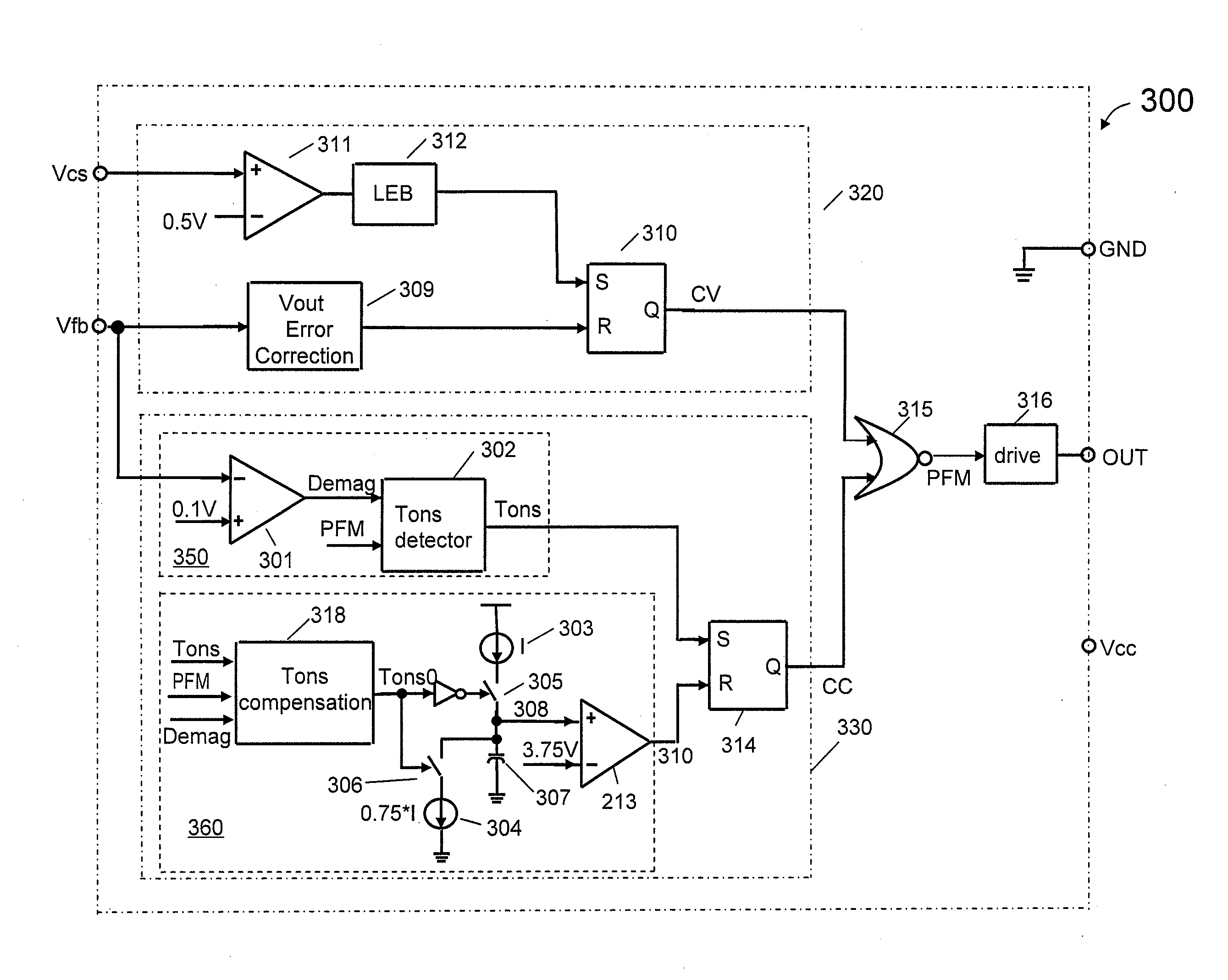
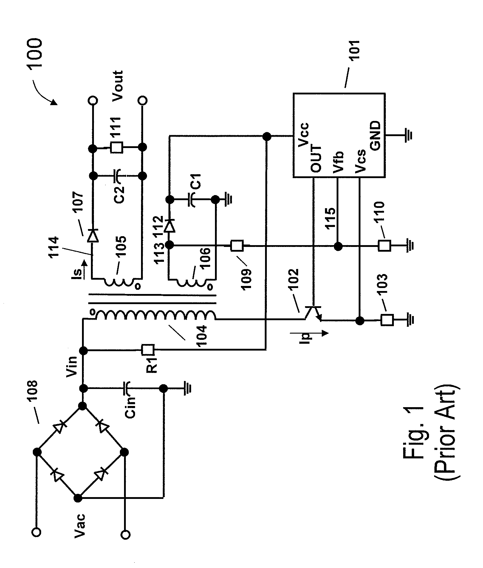
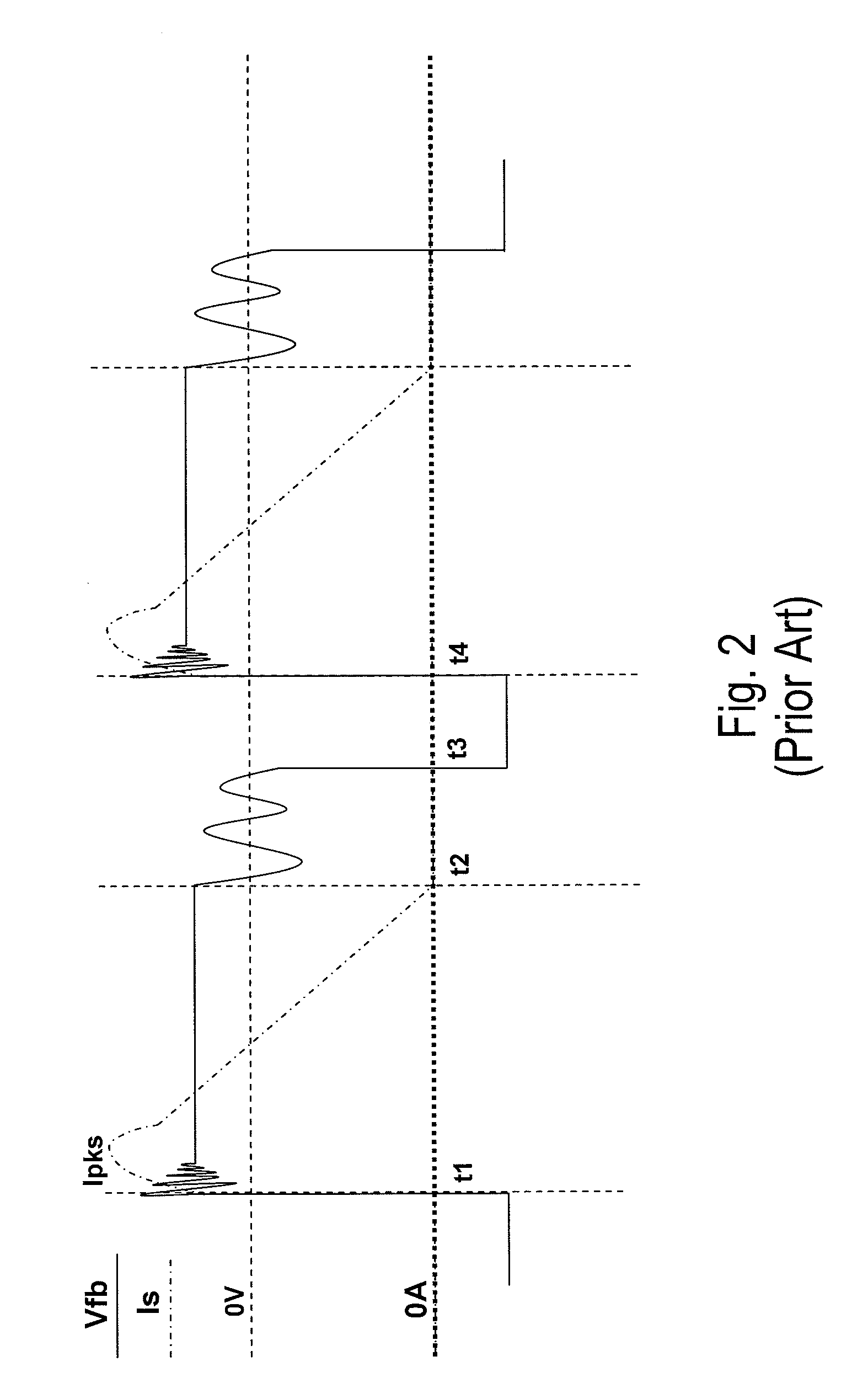
[0040]FIG. 1 is a circuit diagram of a conventional flyback-type primary side regulated switched mode power supply using a pulse width modulation (PFM) control. The primary side regulated switched mode power supply includes a rectifier 108 that converts an AC mains voltage to an unregulated voltage Vin. A capacitor Cin smoothes voltage Vin, which is then applied to a terminal of a primary winding 104. The another terminal of primary winding 104 is coupled to a transistor 102, which is turned on and off by a signal OUT of a PFM controller 101. When transistor 102 is turned on, a primary current Ip flows through primary winding 104, which starts building up a magnetic energy. A secondary winding 105 is magnetically coupled to primary winding 104 and includes a diode 107 and a capacitor C2, which has a relatively high capacity to stabilize the variation of a voltage Vout applying to a load 111. The polarity (winding sense) of secondary winding 105 is such that the magnetic field produc...


PUM


Abstract

A controller for providing a constant output current control signal in a switched mode power supply (SMPS) includes a conduction time compensation circuit that is configured to produce a compensated conduction time interval signal that includes compensation for a ringing waveform of a feedback signal. The compensated signal reflects more accurately the actual conductive time of a rectifying diode in a secondary winding of the switched mode power supply. In one embodiment, the compensated conduction time interval signal is used to generate a fixed ratio between the conduction time and the non-conduction time of the rectifying diode. In another embodiment, the controller also provides a constant voltage control signal.

Description

CROSS-REFERENCES TO RELATED APPLICATIONS[0001]This application is also related to U.S. patent application Ser. No. 12 / 136,760, filed Jun. 10, 2008, commonly owned and incorporated by reference herein.BACKGROUND OF THE INVENTION[0002]This application claims the benefit of China Patent Application No. 200910129471.1 filed Mar. 20, 2009, commonly owned and incorporated by reference herein.[0003]Embodiments of the present invention are directed to power supply control circuits and power supply systems. More particularly, embodiments of the invention provide methods and circuits for controlling an output current in a switched mode power supply (SMPS). Merely by way of example, some embodiments of the invention have been applied to an SMPS constant current controller, such that the output current is substantially independent of variations of AC mains and / or of variations in an output voltage. But it would be recognized that the invention has a much broader range of applicability.[0004]Reg...

Claims


Application Information

Patent Timeline
IPC IPC(8): H02M3/335
CPCH02M3/33523
Inventor FEI, RUIXIASUN, TAOSU, QINGHUAZHU, HUIZHEN
Owner BCD SHANGHAI MICRO ELECTRONICS CO LTD
Why Eureka
Try Eureka