Receiving apparatus

a technology of receiving apparatus and receiving terminal, which is applied in the direction of digital transmission, line-transmission details, television systems, etc., can solve the problems of increasing the total cost of the receiving terminal and the external unit, the deterioration of the characteristics of the signals obtained by each transceiver circuit, and the need for additional parts to be mounted on the receiving terminal. achieve the effect of desirable antenna characteristics

Active Publication Date: 2010-09-23
SONY SEMICON SOLUTIONS CORP
View PDF6 Cites 22 Cited by
  • Summary
  • Abstract
  • Description
  • Claims
  • Application Information

AI Technical Summary

Benefits of technology

[0014]According to an embodiment of the present invention, even if the other signals which frequencies overlap the frequency of the received high frequency signal are transmitted on the connector cable that is also used for the antenna, the desirable antenna characteristics can be obtained. In addition, it is not necessary to prepare plural cables even if a connector is used in common with the received high frequency signal and the other signals.

Problems solved by technology

There are, however, following problems about the above methods.
As for the method to use the signal distributor, there is a problem in that the power of signals input to each transceiver circuit is half the power of the original signals, which results in the deterioration of the characteristics of the signals obtained by each transceiver circuit.
As for the method to use the external unit, there is a problem in that, although the body of the receiving terminal can be downsized, the total cost of the receiving terminal and the external unit rises and additional parts have to be mounted on the receiving terminal.
In addition, there is another problem in that a user has to take along the external unit with him / her, which brings about an inconvenience from the viewpoint of portability.
The above-described techniques do not provide a desirable antenna characteristics when other signals, which frequencies overlap the frequency of the received high frequency signal, are transmitted on a connector cable that is used for an antenna.

Method used


Image

  • Receiving apparatus
  • Receiving apparatus
  • Receiving apparatus

Examples


first embodiment

1. the Present Invention

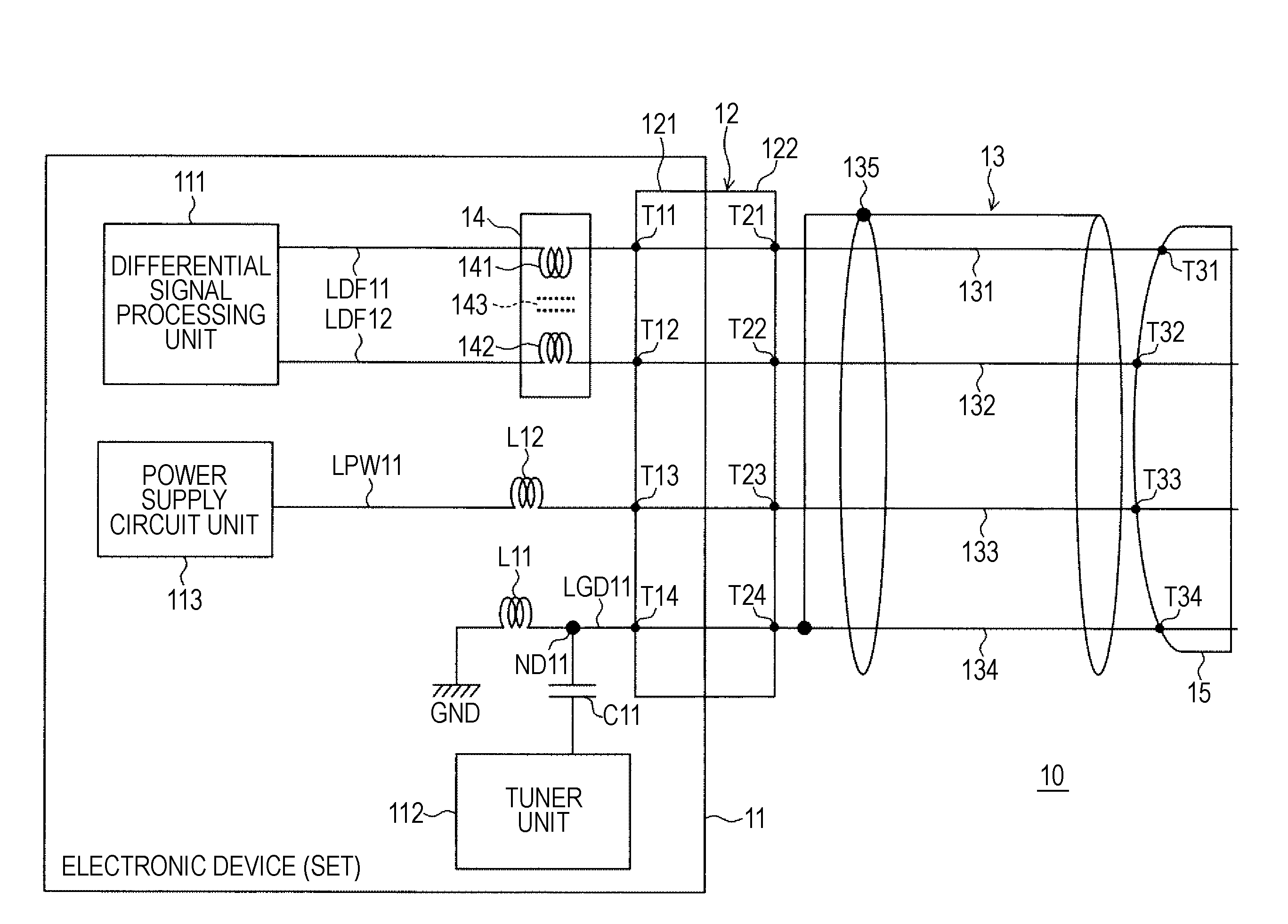
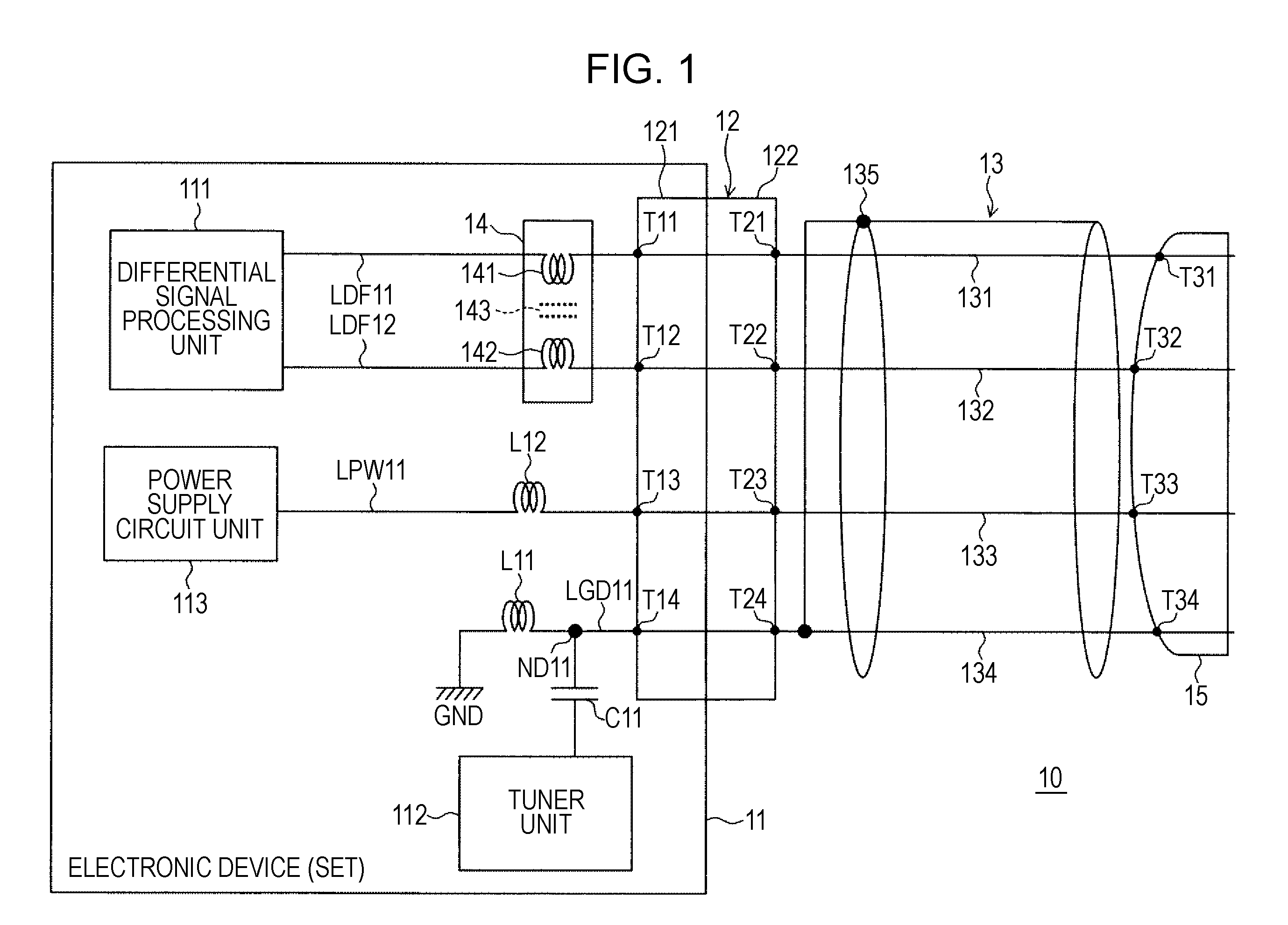
[0034]FIG. 1 is a diagram showing the configuration of the receiving apparatus according to the first embodiment of the present invention.

[0035]This receiving apparatus 10 includes an electronic device (set) 11, a connector 12, a multi-core shielded cable 13 used as a transmission cable, a common mode choke 14, and a second connector 15.

[0036]The electronic device 11 includes a differential signal processing unit 111, a tuner unit 112, a power supply circuit unit 113, differential signal transmission lines LDF11 and LDF12, a ground line LGD11 in the electronic device, a power supply line LPW11, and a capacitor C11. In addition, the electronic device 11 includes inductors L11 and L12 used as high frequency cutoff elements.

[0037]The differential signal processing unit 111 is connected to the connector 12 through the differential signal transmission lines LDF11 and LDF12. The common mode choke (coil) 14 is installed across the differential signal transmission li...

second embodiment

2. the Present Invention

[0065]FIG. 6 is a diagram showing the configuration of a receiving apparatus according to the second embodiment of the present invention.

[0066]The receiving apparatus 10A of this second embodiment is different from the receiving apparatus 10 of the first embodiment in that a common mode choke 14 is installed not inside an electronic device 11A but across core lines 131 and 132 of a multi-core shielded cable 13. In addition, in the receiving apparatus 10A of this second embodiment, an inductor L12 used for a power supply circuit 113 is also installed not inside the electronic device 11A but on a core line 133 of the multi-core shielded cable 13.

[0067]In this way, in the receiving apparatus 10A of this second embodiment, the elements used for separating signals are not installed in the electronic device 11A, but installed across or on the core lines of the multi-core shielded cable 13 in order to downsize the electronic device 11A.

[0068]The other units and elem...

third embodiment

3. the Present Invention

[0069]FIG. 7 is a diagram showing the configuration of a receiving apparatus according to a third embodiment of the present invention.

[0070]The receiving apparatus 10B of this third embodiment is different from the receiving apparatus 10A of the second embodiment in that a multi-core shielded cable 13B is divided into an antenna cable section 13-1 that works as an antenna and a shielded cable section 13-2.

[0071]As shown in FIG. 7, the antenna cable section 13-1 is installed nearer to a second connector 15 used for connection to an external device than the shielded cable section 13-2. In addition, there are following differences between the third embodiment and the second embodiment. An inductor L13 for cutting off high frequencies is installed on a part of a core line 134 that is located between the antenna cable section 13-1 and the shielded cable section 13-2. A shield section 135-1 of the antenna cable section 13-1 is connected to a part of the core line 1...


PUM


Abstract

A receiving apparatus includes: an electronic device; a connector provided to the electronic device; and a transmission cable connected to the connector. The electronic device includes a tuner unit that receives broadcast waves; and a differential signal processing unit that sends and receives data with the use of differential signals. The tuner unit and the differential signal processing unit are connected to the connector. The transmission cable includes at least two transmission lines that transmit differential signals, and the at least two transmission lines are capacitively coupled with each other at high frequency bands owing to capacitances among the at least two transmission lines. In addition, there is at least one common mode choke across two differential signal transmission lines inside the electronic device.

Description

BACKGROUND OF THE INVENTION[0001]1. Field of the Invention[0002]The present invention relates to receiving apparatuses that receive, for example, broadcast waves.[0003]2. Description of the Related Art[0004]In recent years, various kinds of communication terminals, as typified by a cellular phone, that have functions for receiving broadcast waves of FM radio, digital radio or television have become widely used.[0005]The electrical length of an antenna of a communication terminal for receiving, for example, FM broadcast waves are typically 3 m or so. Therefore, the size of the antenna is very large compared with the size of the body of the communication terminal for receiving FM broadcast waves. In contrast, the bodies of the receiving terminals for receiving broadcast waves have been becoming thinner and more reduced in size year by year.[0006]One effective means for solving this unbalanced relation between the size of the antenna and the size of the body of the communication termin...

Claims


Application Information

Patent Timeline
Patent Type & Authority Applications(United States)
IPC IPC(8): H04B3/00H01Q1/46H04B1/18H04N5/44
CPCH01Q1/242H04B3/30H01Q1/44H01Q1/273
Inventor KOMORI, CHISATOYOSHINO, YOSHITAKAMUKAI, KOICHI
Owner SONY SEMICON SOLUTIONS CORP
Why Eureka
Try Eureka