Optical line terminal, passive optical network system, and bandwidth assignment method

a technology of optical network system and optical line terminal, applied in the direction of time-division multiplex, multiplex communication, electrical apparatus, etc., can solve the problems of large influence of data delay in the pon, inability to increase throughput, and increase window size, etc., to achieve the effect of maximizing throughpu

Inactive Publication Date: 2010-09-23
HITACHI LTD
View PDF2 Cites 41 Cited by
  • Summary
  • Abstract
  • Description
  • Claims
  • Application Information

AI Technical Summary

Benefits of technology

[0030]In other words, advantages obtained by the typical aspects of the invention are that a communication service capable of maximizing throughput for each

Problems solved by technology

In the 10 Gbps-class PON, however, if the bandwidth assignment period is constant, data delay is also constant, which causes a problem that the throughput cannot be increased if such a data transfer protocol as to confirm whether data can be transferred like the TCP.
At this point, the i

Method used


Image

  • Optical line terminal, passive optical network system, and bandwidth assignment method
  • Optical line terminal, passive optical network system, and bandwidth assignment method
  • Optical line terminal, passive optical network system, and bandwidth assignment method

Examples


first embodiment

[0047]The PON system of the first embodiment according to the present invention is described below based on FIGS. 1 to 8.

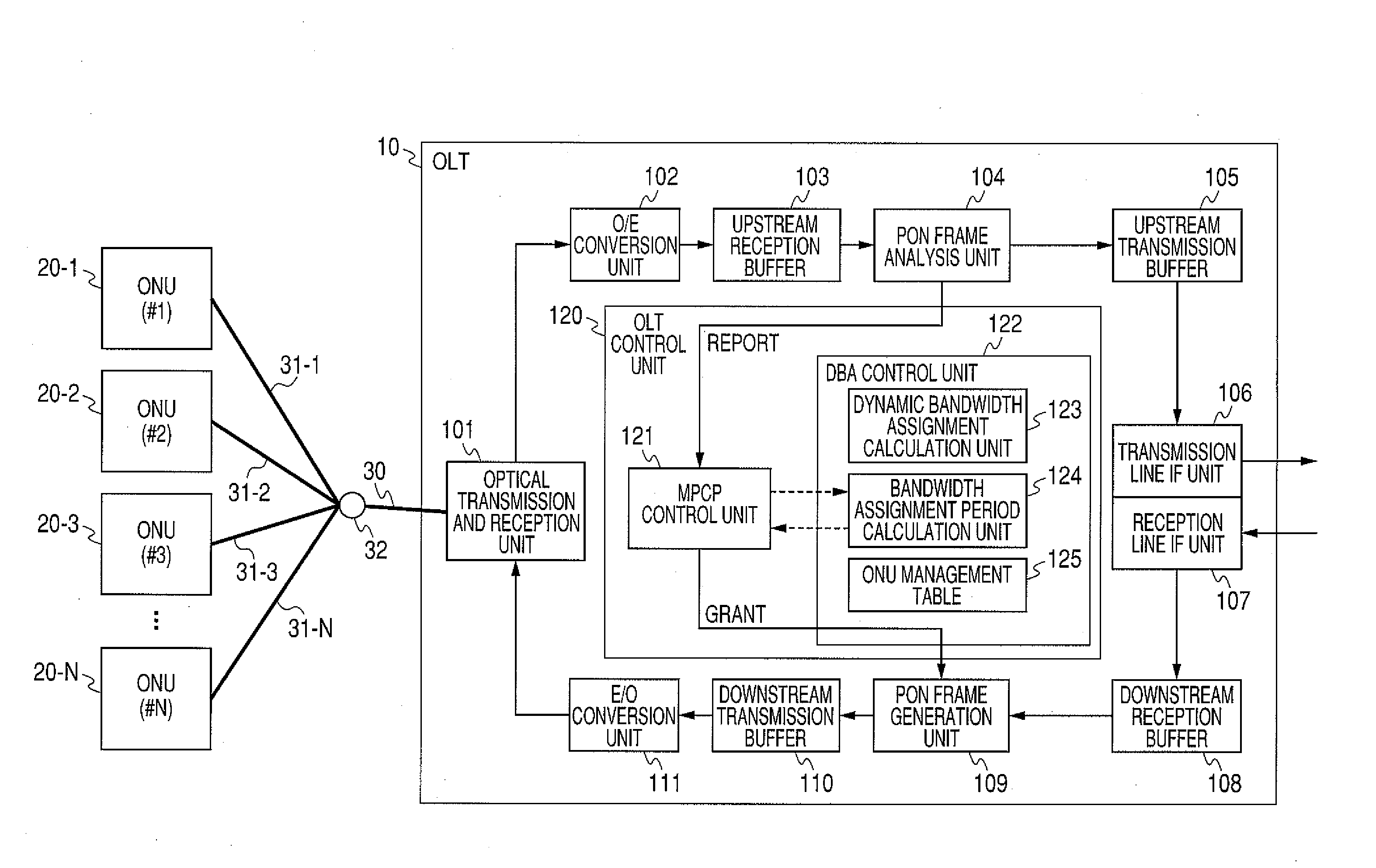
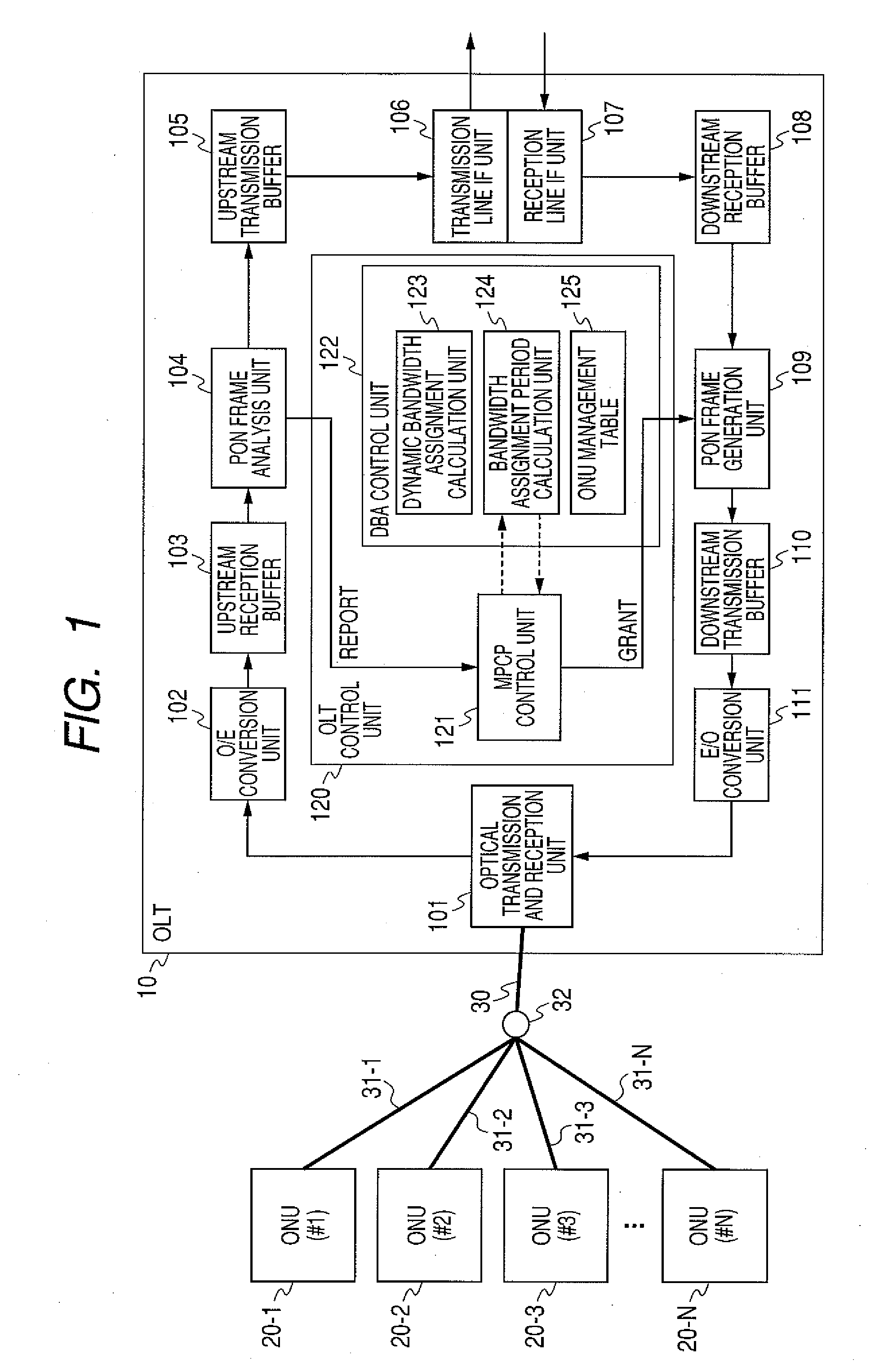
[0048]FIG. 1 is a block diagram showing a configuration of a PON system of the first embodiment according to the present invention.

[0049]The PON system includes an OLT (also referred to as a station-side device or an optical line terminal) 10, a plurality of ONUs (also referred to as a user's home-side device or an optical network unit) 20 (#1: 20-1, #2: 20-2, #3: 20-3, . . . , #N: 20-N), and an optical distribution network (ODN) in a PON section for connecting these elements. The optical distribution network in the PON section includes a concentration optical fiber 30 connected to the OLT 10 and stay optical fibers 31 (31-1 to 31-N) connected to the ONUs 20. The stay optical fibers 31 are branched from the concentration optical fiber 30 by an optical splitter (or an optical coupler) 32. The OLT 10 is generally installed in a user-line accommodation station owned ...

second embodiment

[0079]The PON system of the second embodiment according to the present invention is described below based on FIGS. 9 and 10.

[0080]FIG. 9 is a block diagram showing an internal configuration of an ONU of the second embodiment according to the present invention. The example of FIG. 9 includes a service identification unit 212 with a function of service identification means for identifying and classifying kinds of service of data received from a user terminal and transferring the data between a PON frame generation unit 209 and an upstream transmission buffer 210. The upstream transmission buffer 210 includes a buffer for TCP data 213, a buffer for UDP data 214, and a selector 215. Other components are similar to those in the above first embodiment.

[0081]The service identification unit 212 identifies the received packets, classifies them to corresponding buffers and transfer the packets. The MPCP control unit 221 notifies the OLT 10 of the amount of data storage in the buffer for TCP d...

third embodiment

[0084]The PON system of the third embodiment according to the present invention is described below based on FIG. 11.

[0085]FIG. 11 is a flow chart showing the process of a DBA function of the third embodiment according to the present invention. The present embodiment is an example showing that the throughput of the ONU 20 can be optimized also by receiving a data delay request from each ONU 20.

[0086]In step S701, the MPCP control unit 121 receives a request for data delay from the ONU 20 and updates the ONU management table 125. In step S702, the dynamic bandwidth assignment calculation unit 123 calculates an assignment bandwidth based on information of the ONU management table 125. In step S703, the bandwidth assignment period calculation unit 124 calculates a bandwidth assignment period based on information of the ONU management table 125. In step S704, the MPCP control unit 121 notifies the ONU 20 of the transmission allowance (grant) including the bandwidth information assigned t...


PUM


Abstract

An OLT of a station-side device in a PON system, the OLT including: an MPCP control unit for receiving bandwidth requirements from each of a plurality of ONUs of home-side devices; a bandwidth assignment period calculation unit for calculating the following bandwidth assignment period for each request source based on the received bandwidth requirements for each request source; a dynamic bandwidth assignment calculation unit for calculating the following bandwidth assignment for each request source based on the received bandwidth requirements for each request source; and the MPCP control unit for transmitting transmission allowance based on the calculated bandwidth assignment to each of the plurality of ONUs.

Description

CLAIM OF PRIORITY[0001]The present application claims priority from Japanese patent application JP 2009-065463 filed on Mar. 18, 2009, the content of which is hereby incorporated by reference into this application.FIELD OF THE INVENTION[0002]The present invention relates to a high-speed optical access network and, more specifically, to a technique effectively applied to a passive optical network (PON) system capable of providing a high-speed Internet service for home through an optical fiber and an optical line terminal being a station-side device applied to the PON system.BACKGROUND OF THE INVENTION[0003]According to the inventors' investigation, in the PON system, the speed and the bandwidth of a communication network are being increased to transmit and receive a large amount of image signals or data even in an access network for connecting a subscriber to a communication network. The PON system specified by the recommendation G984.1-3 of the International Telecommunication Union ...

Claims


Application Information

Patent Timeline
IPC IPC(8): H04J14/00
CPCH04J3/1694
Inventor IKEDA, HIROKIKAZAWA, TOHRU
Owner HITACHI LTD
Why Eureka
Try Eureka