Rotation Detecting Device and Rotation Detecting Method

a detection device and rotation detection technology, applied in the direction of machines/engines, electrical control, instruments, etc., can solve the problem of reducing the accuracy of determination of normal rotation/reverse rotation based on the comparison between the measured value of pulse width and the threshold value, and achieve the effect of keeping stable determination accuracy

Active Publication Date: 2010-09-23
HITACHI ASTEMO LTD
View PDF25 Cites 30 Cited by
  • Summary
  • Abstract
  • Description
  • Claims
  • Application Information

AI Technical Summary

Benefits of technology

[0006]Therefore, an object of the present invention is to provide a rotation detecting device and a rotation detecting method capable of keeping stable accuracy of determination of normal rotation / reverse rotation of a rotating shaft.

Problems solved by technology

However, if the pulse width of the rotation signal varies due to variation between detectors or deterioration of the detector, it reduces accuracy of determination of the normal rotation / reverse rotation based on comparison between the measured value of the pulse width and the threshold value.

Method used


Image

  • Rotation Detecting Device and Rotation Detecting Method
  • Rotation Detecting Device and Rotation Detecting Method
  • Rotation Detecting Device and Rotation Detecting Method

Examples


Embodiment Construction

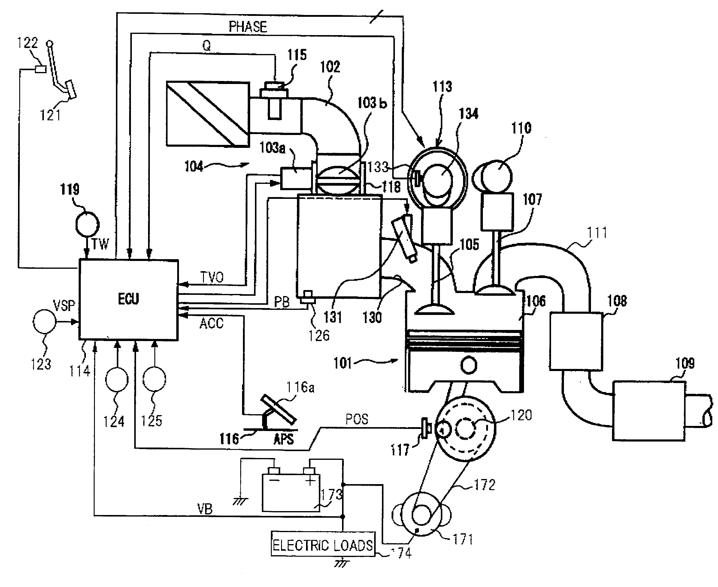
[0017]FIG. 1 is a view showing an internal combustion engine 101 for a vehicle and a rotation detecting device and a rotation detecting method according to the invention of the present application is applied to internal combustion engine 101. In the embodiment, internal combustion engine 101 is an in-line four-cylinder engine.

[0018]In FIG. 1, in an intake pipe 102 of internal combustion engine 101, an electronically-controlled throttle 104 in which a throttle valve 103b is driven to open and close by a throttle motor 103a is disposed.

[0019]Internal combustion engine 101 sucks air into a combustion chamber 106 of each cylinder through electronically-controlled throttle 104 and an intake valve 105.

[0020]A fuel injection valve 131 is provided in an intake port 130 of each cylinder. Fuel injection valve 131 opens and injects fuel in response to an injection pulse signal from an ECU (engine control unit) 114.

[0021]Fuel in combustion chamber 106 is ignited and burned by spark ignition by ...


PUM


Abstract

A rotation detecting device and a rotation detecting method determines normal rotation/reverse rotation of a rotating shaft based on a rotation signal different between the normal rotation and the reverse rotation of the rotating shaft. The rotation signal is set to have a pulse width different between the normal rotation and the reverse rotation of a crankshaft that is an output shaft of an internal combustion engine. By determining whether or not the pulse width is greater than a threshold value, the normal rotation or the reverse rotation of the crankshaft is detected. Whether or not the crankshaft is rotating normally is determined based on engine rotating speed, a cylinder in which a piston is in a predetermined position, an engine load, a starter switch, intake pressure, battery voltage, and the like. When the condition for the normal rotation is satisfied, the threshold of the pulse width is set based on a pulse width of a rotation signal measured at this time.

Description

BACKGROUND OF THE INVENTION[0001]1. Field of the Invention[0002]The present invention relates to a rotation detecting device and a rotation detecting method for determining normal rotation / reverse rotation of a rotating shaft based on rotation signals different between normal rotation and reverse rotation of the rotating shaft.[0003]2. Description of Related Art[0004]In Japanese Laid-open (Kokai) Patent Application Publication No. 2009-002193, an engine control apparatus including a detector for outputting rotation signals in synchronization with rotation of a crankshaft of an engine, is disclosed. Here, the detector outputs the rotation signals of different pulse widths depending on whether the crankshaft is rotating normally or reversely. The control apparatus measures the pulse width of the rotation signal and determines the normal rotation / reverse rotation of the crankshaft based on whether or not the measured value of the pulse width is greater than a threshold value.[0005]Howe...

Claims


Application Information

Patent Timeline
Patent Type & Authority Applications(United States)
IPC IPC(8): G06F19/00F02D45/00
CPCF01L1/34403F01L13/0026G01P13/045F02D2250/06F02D41/009
Inventor SHIMIZU, HIROKAZU
Owner HITACHI ASTEMO LTD
Why Eureka
Try Eureka