Method and Apparatus to Effect Heat Transfer

a heat exchanger and heat exchange technology, applied in lighting and heating apparatus, heat recovery, greenhouse gas reduction, etc., can solve the problems of large quantities of byproduct heat or waste heat, inefficiency that is commonly accepted as the norm, and difficult to find useful applications, so as to reduce the discharge of pollutants, reduce the effect of heat dissipation to atmosphere, and effective heat capture and utilization

Inactive Publication Date: 2010-09-30
PRICE RICHARD J
View PDF37 Cites 19 Cited by
  • Summary
  • Abstract
  • Description
  • Claims
  • Application Information

AI Technical Summary

Benefits of technology

[0012]The disclosed devices seek to effect heat transfer to be employed for one or more uses or to one or more media. In addition, the disclosed devices seek to reduce the discharge of pollutants from primary combustion processes by implementing secondary combustion processes. With more effective heat capture and utilization, the disclosed heat exchange technologies provide methods and apparatus to reduce heat dissipation to atmosphere.

Problems solved by technology

Mechanisms for conversion of energy contained in fuels to mechanical work or electric energy necessarily produce large quantities of byproduct heat or waste heat.
Although engineers have attempted to understand and control the flow of heat through the use of thermal insulation, heat exchangers, and other devices, it is well known that inefficiency has commonly been accepted as the norm.
In addition, it is often difficult to find useful applications for the large quantities of low quality waste heat from these systems so the solution has been to reject waste heat to the environment.
This of course results in dissipative heating of the water body which may also be an environmental detriment.
If sufficient cooling water is not available, the power plant would require cooling tower technology to reject waste heat to atmosphere.
Although waste heat can typically be recovered if a cogeneration system is used, the use of byproduct heat is often limited due to difficulties in heat transport and heat storage.
There are huge potentials of waste heat.
Mechanisms for conversion of energy contained in fuels can also produce unwanted pollutants.
In an actual combustion process, however, it is not uncommon for the combustion of the fuel to be incomplete, resulting in unoxidized compounds and unburned fuel in the products.
Although many types of technology are currently available for the production of energy and / or heat, it is asserted that only little progress to conventional technology has been achieved over the last centuries because of the availability of cheap fuel sources.
This can result in use of less fuel, which can lead to less pollution and a decrease in system operating costs.

Method used


Image

  • Method and Apparatus to Effect Heat Transfer
  • Method and Apparatus to Effect Heat Transfer
  • Method and Apparatus to Effect Heat Transfer

Examples


embodiment 100

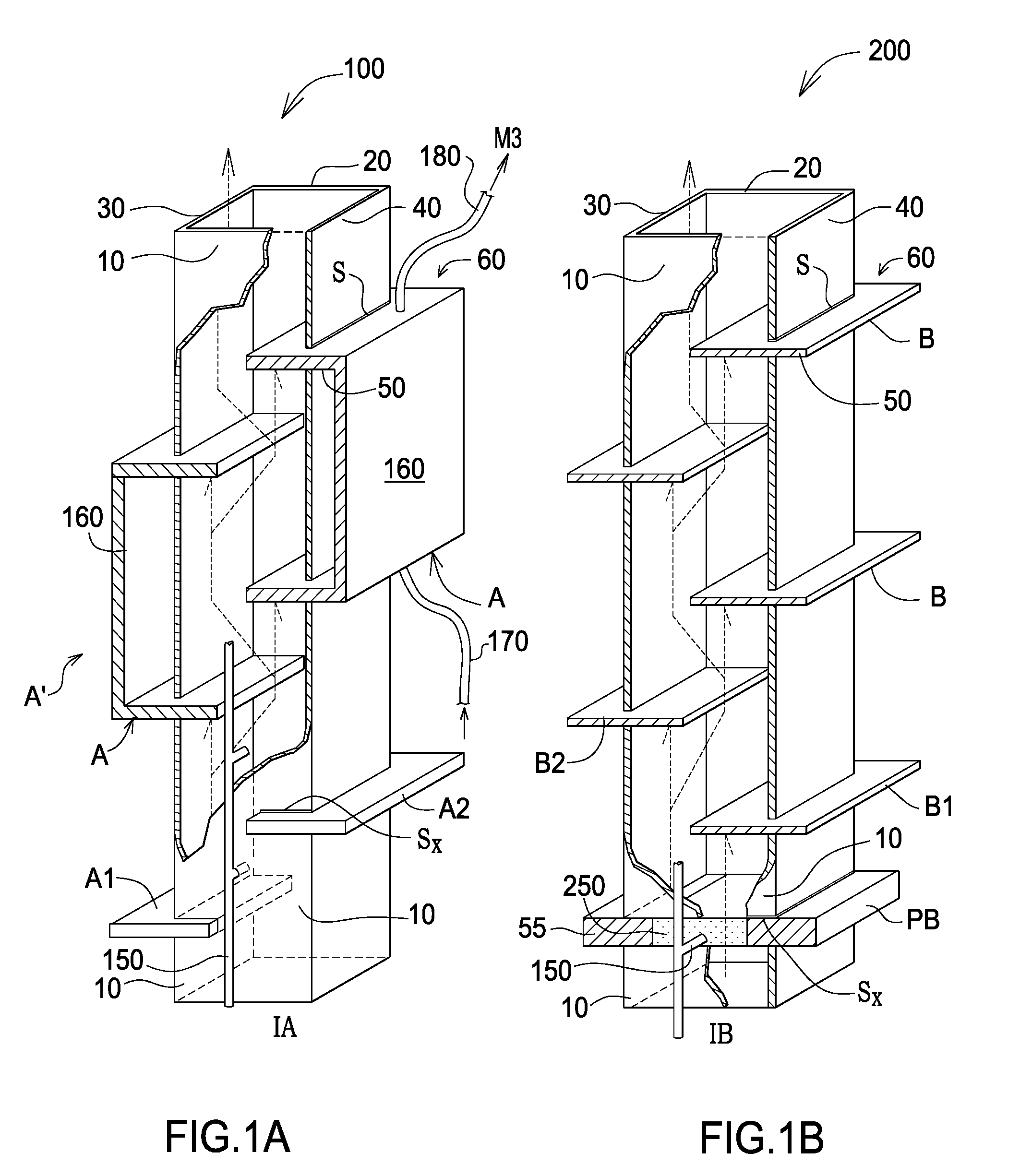
[0062]Embodiment 100 receives combustion gases from a combustion unit (not shown). The A series of fins originate from an inner portion of device 100 and extend outwardly through each of walls 10, 20, 30 or walls 10, 20, 40. Combustion core inlet IA is offset from fin A1. Flow from core inlet IA is directed in a substantially serpentine path as bounded by the A series of fins and as shown conceptually by the dotted lines and arrows. Not only do the fins collect and conduct thermal energy, they serve to restrict the flow of combustion gases through a unit and can be used to promote turbulence. In all forms, the fin devices close to the source of heat receive heat from the products of combustion delivered from the combustion unit and / or burner, and conduct heat to the designated medium. In an alternate configuration, core inlet IA could be placed directly under fin A1 if required by the particular application.

[0063]To increase the likelihood that combustible substances are joined with...

embodiment 200

[0075]As stated above, the profile of the disclosed fins can be lengthened in directions z and / or (−) z. That of the finned plates can be lengthened in one or more directions x, y, z or directions (−) (x, y, z). In embodiment 200, plate PB extends outwardly in a right to left configuration from side walls 30, 40. Outer front surface 55 of finned plate PB is shown to be substantially flush with the inner surface of the front wall 10. Correspondingly, the outer back surface of the finned plate would be substantially flush with the inner surface of the back wall 20.

[0076]The B series of fins originate from an inner portion of device 200 and extend outwardly through each of walls 10, 20, 30 or walls 10, 20, 40. The fins are mounted in receiving slots S in the side walls of unit 200. The B series of fins jut from side walls 30, 40 in a substantially perpendicular fashion relative to the outer surface of side walls 30, 40. The outer front surfaces 50, 60 of the B series of fins extend out...

embodiment 300

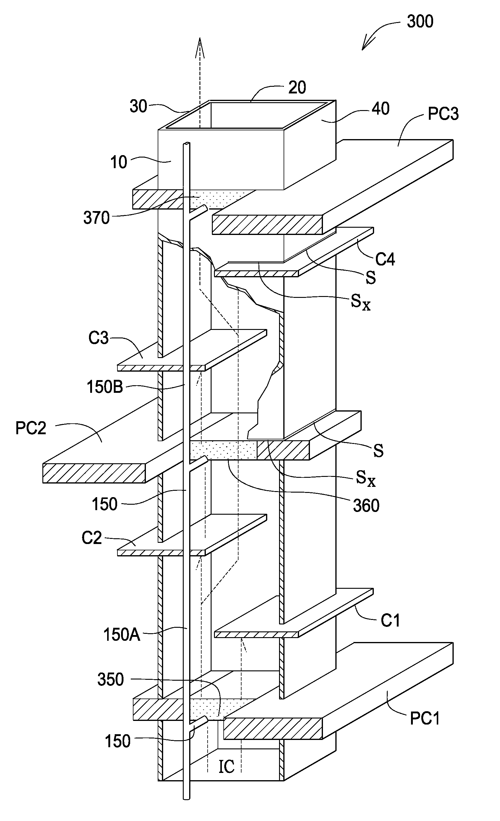
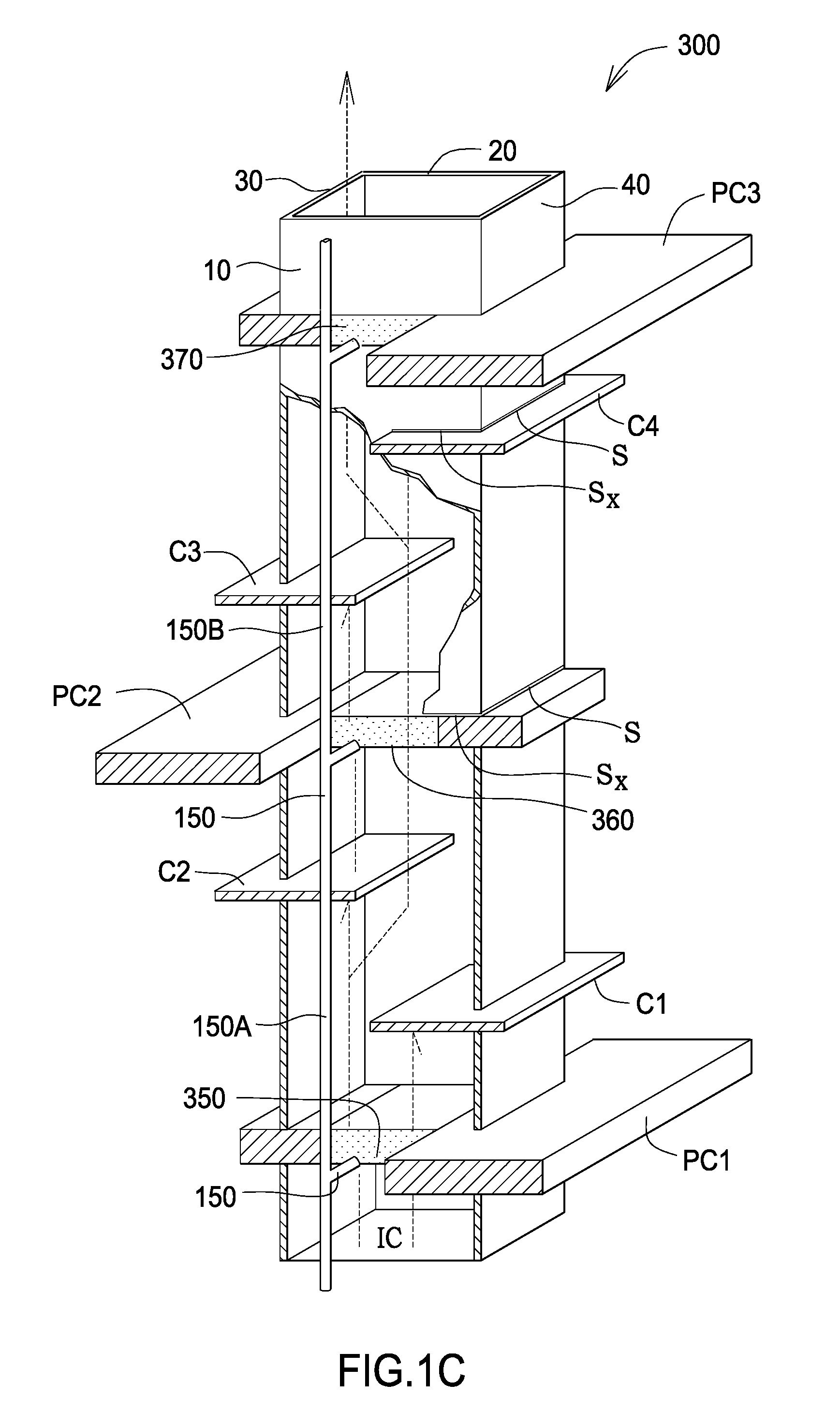
[0089]In FIG. 1C is shown an embodiment 300 comprising walls 10, 20, 30, 40 and a series of thermally conductive fins C1, C2, C3, C4 mounted horizontally in walls 30, 40. Finned plates PC1, PC2 and PC3 extend beyond walls 30, 40. A finned plate PC1 extends across the primary combustion core, the inlet of which is centrally aligned. A discrete stage is formed between finned plates PC1 and PC2 and between PC2 and PC3. As shown, there could be two discrete stages having three sub-stages. Each of the two discrete systems potentially provide for a discrete combustion area. With the appropriate catalytic device(s) and / or excess air, sequential combustion can be achieved. In other words, inlet gas through core ICcould undergo a combustion process at finned plate PC1. Heat capture can occur at finned plates PC2, PC3 whereby heat can be transferred to its terminus. Inlet gas could also undergo a combustion process at finned plate PC2 or in the systems bounded by finned plates PC1 and PC2 and...


PUM


Abstract

The disclosed methods and apparatus seek to effect heat transfer through the use of one or more conductive fin devices. In addition, the disclosed devices seek to reduce the discharge of pollutants from primary combustion processes using carbonaceous fuel sources by implementing secondary combustion features and other apparatus. With more effective heat capture and utilization, the disclosed heat exchange technologies provide methods and apparatus to reduce heat dissipation to atmosphere. The methods and apparatus have application in the areas of industrial incineration, power boilers, water heaters, residential and commercial solid fuel waste heat recovery appliances, and electric power generation. In addition, the technology could have application in the areas of solar systems, desalination systems, aircraft and vehicular engines, electric motors, turbines, oil pans on internal combustion engines, transmission cooling pans, cooling navigational and electronic systems, and computer cooling and power supply.

Description

FIELD OF ART[0001]The disclosed apparatus and methods relate generally to the field of plate-type heat exchangers which can be conjoined with secondary combustion devices, and more specifically to such apparatus which are stand-alone devices or incorporated into one or more systems of devices.BACKGROUND[0002]Mechanisms for conversion of energy contained in fuels to mechanical work or electric energy necessarily produce large quantities of byproduct heat or waste heat. Presently, technology may utilize one or more heat exchangers to effect heat transfer from one medium to another. Although engineers have attempted to understand and control the flow of heat through the use of thermal insulation, heat exchangers, and other devices, it is well known that inefficiency has commonly been accepted as the norm. For example, it is well known that most of the time the electrical efficiency of thermal power plants, which is defined as the ratio between the input and output energy, only amounts ...

Claims


Application Information

Patent Timeline
Patent Type & Authority Applications(United States)
IPC IPC(8): F28F7/00F23M9/00
CPCF23J15/06Y02E20/363F23M9/003Y02E20/30
Inventor PRICE, RICHARD J.
Owner PRICE RICHARD J
Why Eureka
Try Eureka