Ion radiation damage prediction method, ion radiation damage simulator, ion radiation apparatus and ion radiation method

a simulation and simulation technology, applied in the direction of material analysis using wave/particle radiation, fluid pressure measurement, nuclear engineering, etc., can solve the problem of difficult to measure the distribution within a realistic measurement time period, and achieve the effect of reducing development costs, reducing simulation time, and reducing evaluations of these processes

Active Publication Date: 2010-09-30
SONY CORP
View PDF6 Cites 29 Cited by
  • Summary
  • Abstract
  • Description
  • Claims
  • Application Information

AI Technical Summary

Benefits of technology

[0026]Since the ion radiation damage prediction method provided by the embodiment of the present invention allows the simulation time to be shortened considerably, the ion radiation damage prediction method offers a merit that the turn around time (TAT) of the developments of a Complementary Metal Oxide Semiconductor (CMOS) device process and an image sensor process as well as the evaluations of these processes can be shortened so that the development cost can be reduced.
[0027]Since the ion radiation damage simulator provided by the embodiment of the present invention allows the simulation time to be shortened considerably, the ion radiation damage prediction method offers a merit that the TAT of the developments of a CMOS device process and an image sensor process as well as the evaluations of these processes can be shortened so that the development cost can be reduced.
[0028]Since the ion radiation apparatus provided by the embodim...

Problems solved by technology

It is to be noted that, by merely carrying out experiments, it is diffic...

Method used


Image

  • Ion radiation damage prediction method, ion radiation damage simulator, ion radiation apparatus and ion radiation method
  • Ion radiation damage prediction method, ion radiation damage simulator, ion radiation apparatus and ion radiation method
  • Ion radiation damage prediction method, ion radiation damage simulator, ion radiation apparatus and ion radiation method

Examples


first embodiment

1. First Embodiment

[First Typical Example of an Ion Radiation Damage Prediction Method]

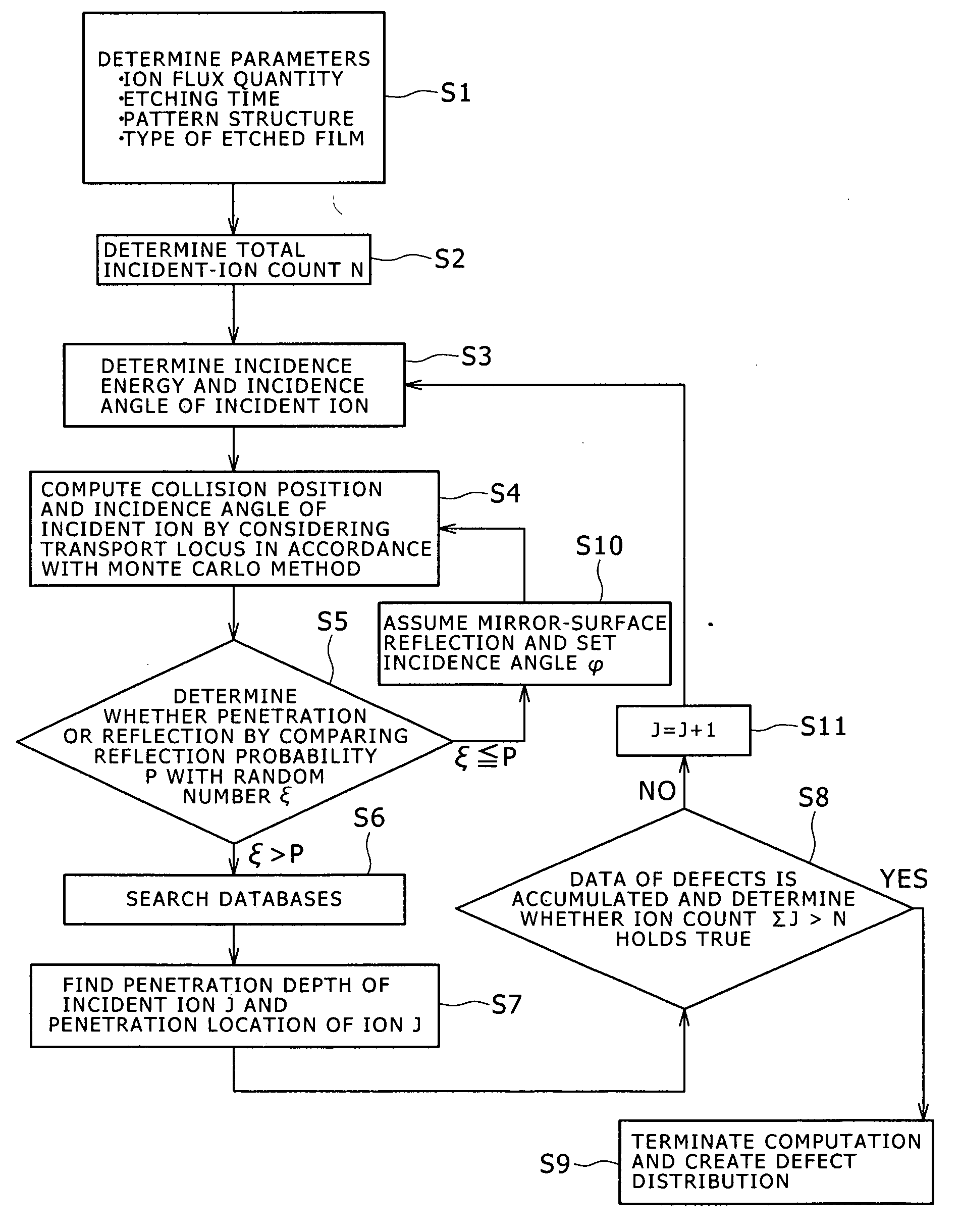
[0049]A first typical example of an ion radiation damage prediction method according to a first embodiment of the present invention is explained by referring to a flowchart shown in FIG. 1.

[0050]As shown in the flowchart of FIG. 1, first of all, a parameter computation step is carried out. At the parameter computation step, the collision position of an incident ion incoming to a fabricated object and the incidence angle of the incident ion are computed by consideration of a transport path traced by the incident ion as a path to the fabricated object and by adoption of the Monte Carlo method which takes a distribution of flux quantities of incident ions, a distribution of incidence energies of incident ions and a distribution of incidence angles of incident ions as input parameters.

[0051]To put it more concretely, the parameter computation step is carried out as follows. At the first step S1, input...

second embodiment

2. Second Embodiment

[Typical Ion Radiation Damage Simulator]

[0186]A typical example of an ion radiation damage simulator according to a second embodiment of the present invention is explained as follows.

[0187]The typical example of the ion radiation damage simulator includes:

[0188]a processing section configured to carry out computation to predict defects generated in a fabricated object due to incident ions radiated to the fabricated object; and

[0189]an output section configured to output a distribution of the defects computed by the processing section as a distribution of defects generated in the fabricated object due to incident ions radiated to the fabricated object.

[0190]The processing section carries out the computation to predict defects by adoption of any one of the computation algorithms each explained earlier as an algorithm of one of the first to third typical examples of the ion radiation damage prediction method according to the first embodiment of the present invention...

third embodiment

3. Third Embodiment

[First Example of an Ion Radiation Apparatus]

[0192]A first example of an ion radiation apparatus according to a third embodiment of the present invention is explained by referring to a block diagram of FIG. 13.

[0193]As shown in the block diagram of FIG. 13, the first example of the ion radiation apparatus is a dry etching apparatus 400 which employs a shape simulator 410 for predicting shape changes generated in an etching fabrication process as changes of the shape of a fabricated object serving as the subject of the etching fabrication process. In addition, the dry etching apparatus 400 also employs an ion radiation damage simulator 420 for predicting damages caused by radiation of ions in the etching fabrication process by referring to the shape changes predicted by the shape simulator 410 as shape data of the fabricated object.

[0194]On top of that, the dry etching apparatus 400 also employs a control section 430 and an etching process section 440. The control ...


PUM

PropertyMeasurementUnit
Electrical conductivityaaaaaaaaaa
Shapeaaaaaaaaaa
Depthaaaaaaaaaa

Abstract

An ion radiation damage prediction method includes a parameter computation step of computing the collision position and the incidence angle of an incident ion hitting a fabricated object by considering a transport path of the ion and by adopting the Monte Carlo method which takes distributions of flux quantities, incidence energies and angles of incident ions as input parameters; and a defect-distribution computation step of searching for data by referring to information found at the parameter computation step and databases created in advance, the databases storing distributions of quantities of crystalline defects having an effect on the fabricated object, ion reflection probabilities and ion penetration depths, finding the penetration depth and location of the incident ion based on the data found in the search operation, and the incidence energy and angle of the incident ion, and computing a distribution of defects in the fabricated object from the penetration depth and location.

Description

BACKGROUND OF THE INVENTION[0001]1. Field of the Invention[0002]The present invention relates to an ion radiation damage prediction method, an ion radiation damage simulator, an ion radiation apparatus and an ion radiation method.[0003]2. Description of the Related Art[0004]Results of studies have indicated that it is quite within the bounds of possibility that damages caused by incoming ions generated in processing such as an etching process, a physical vapor deposition (PVD) process or an ion injection process to a fabricated film have a big effect on electrical characteristics of the device including the film. Such damages are thus a problem that needs to be solved as quickly as possible. A typical damage caused by incoming ions incident to a processed film serving as a target film of a process generating the ions is a crystalline defect. Thus, the target film including a pattern means a film hit by ions.[0005]By merely making use of the contemporary measurement apparatus, howeve...

Claims


Application Information

Patent Timeline
IPC IPC(8): G06G7/48H01J37/317H01J37/305G06F17/18C23C14/34
CPCG01N23/00H01L21/32137H01J37/3023C23C14/48C23C14/54Y10T428/31
Inventor KUBOI, NOBUYUKIKOBAYASHI, SHOJI
Owner SONY CORP
Why Eureka
Try Eureka