Hot-forming fabrication method and product of magnetic component

a technology of hot-forming fabrication and magnetic components, which is applied in the direction of transformers/inductances, magnetic cores, manufacturing tools, etc., can solve the problems of disadvantaged design of assembling drum cores described above, not enhancing field induction, etc., and achieves high permeability material, low core loss, and high efficiency

Inactive Publication Date: 2010-09-30
CURIE IND
View PDF11 Cites 9 Cited by
  • Summary
  • Abstract
  • Description
  • Claims
  • Application Information

AI Technical Summary

Benefits of technology

[0011]2. Using a low core loss and high permeability material and a highly effective electromagnetic wave shielding material developed by the present invention to further improve the performance of the enhanced energy storage component.

Problems solved by technology

Furthermore, as the magnetic field is diverging, it will not enhance the field induction.
However, the assembling drum core design described above is disadvantaged by gaps 31 (as shown by the hatched areas in FIG. 10) between components of the assembling drum core.

Method used


Image

  • Hot-forming fabrication method and product of magnetic component
  • Hot-forming fabrication method and product of magnetic component
  • Hot-forming fabrication method and product of magnetic component

Examples


embodiment

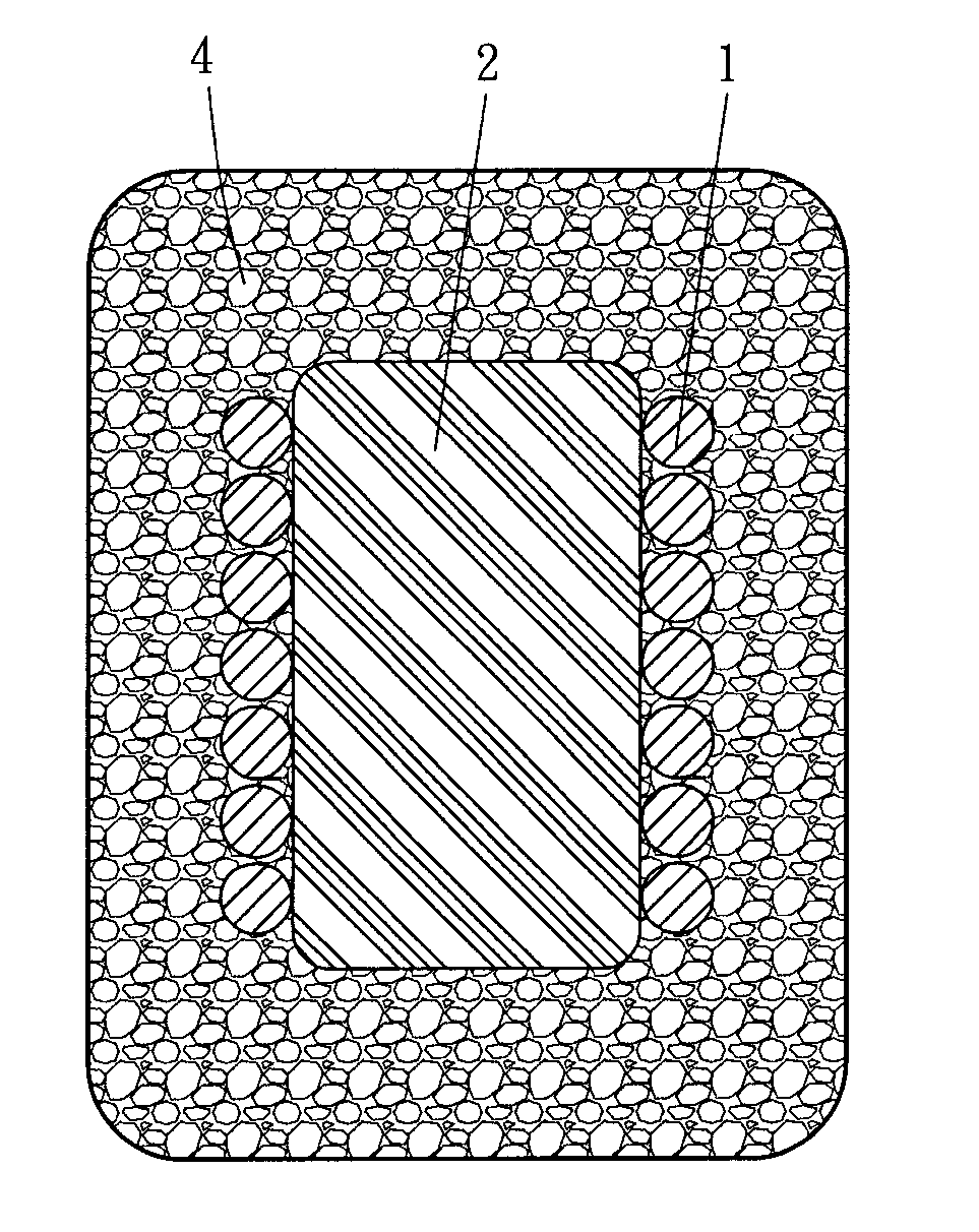
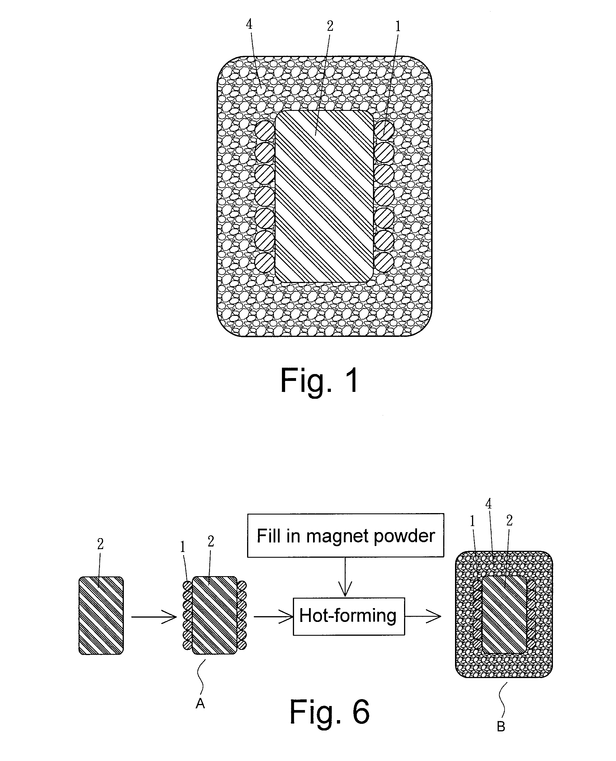
[0094]A surface-mounted device, more particularly a surface-mounted inductor, is exemplified herein as an embodiment of the present invention. The dimensions of the device are shown in FIG. 11A and Table 1.

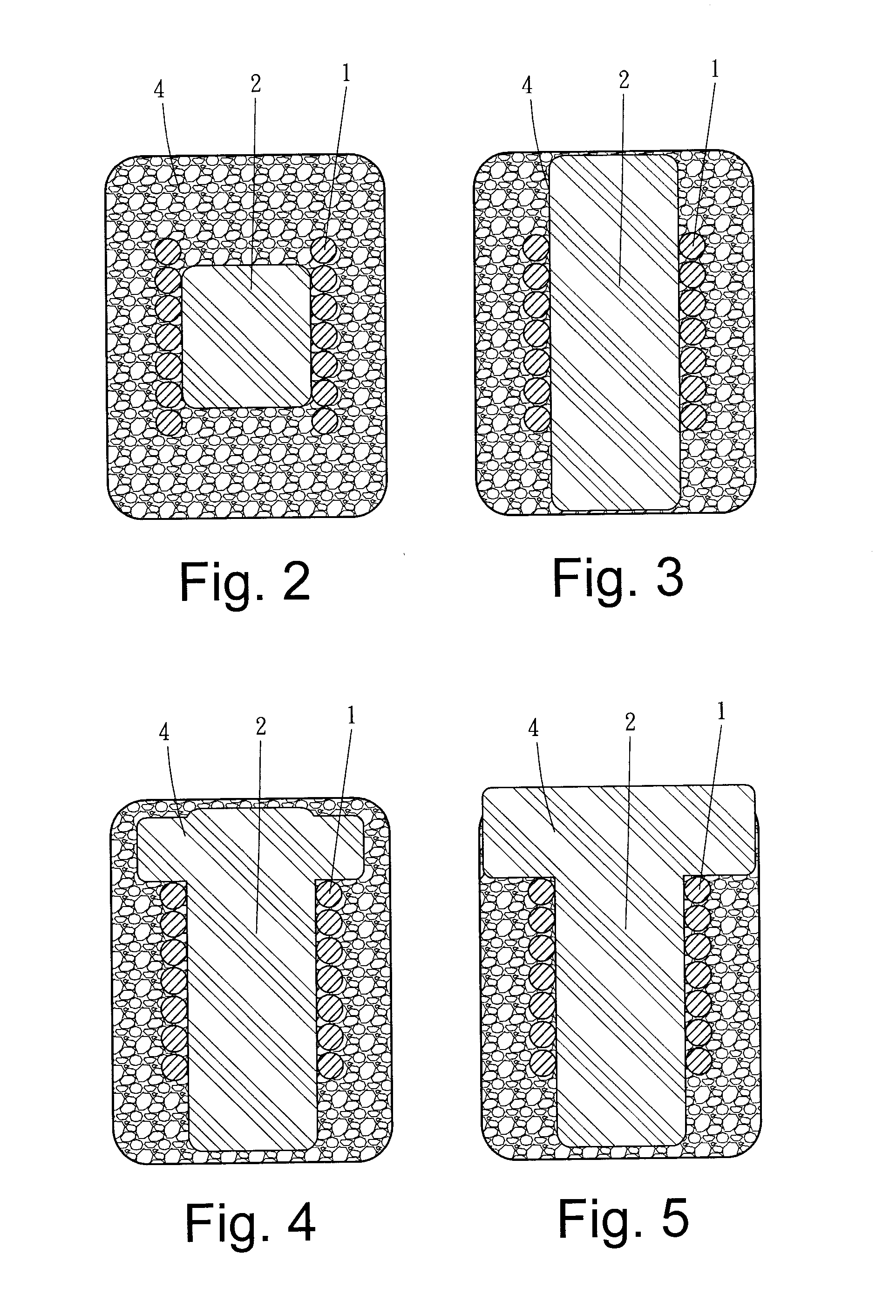
TABLE 1Dimension (mm)DescriptionA12.8Length of deviceB12.8Width of deviceC5.20Height of deviceD9.0Distance between padsE2.3Length of the left padsF2.3Length of the right padsG5Width of the padsHSee note* below.Exposed diameter of iron core 2JMagnetic shielding material 4*The dimension H includes the following three dimensions for use in different experiment conditions, with a view to examining how volume variation of the iron core affects power consumption: X: The diameter is 0 mm, meaning absence of iron core. Y: A columnar iron core, made of a Fe—Al—Si alloy, has a diameter of 4.5 mm and a height of 4.95 mm. Z: A T-shaped iron core has the dimensions indicated in FIG. 11B and is made of a Fe—Al—Si alloy.

[0095]Pictures taken of the finished devices are shown in FIG. 12 in a side ...


PUM

PropertyMeasurementUnit
temperaturesaaaaaaaaaa
thermal decomposition temperatureaaaaaaaaaa
diameteraaaaaaaaaa

Abstract

A hot-forming fabrication method of a magnetic component and a hot-formed magnetic component fabricated by the same are provided. More particularly, a magnetic powder hot-forming technique is provided, along with a hot-formed magnetic component fabricated by the hot-forming technique so as to have high inductance, low core loss, and high electromagnetic wave shielding efficiency. A low core low-core loss core for use in a common basic magnetic component is enclosed and thereby shielded by a single-layer or multi-layer EMI shielding material, thus producing an enhanced magnetic component with high inductance, low core loss, and low electromagnetic wave interference.

Description

BACKGROUND OF THE INVENTION[0001]1. Technical Field[0002]The present invention relates to a hot-forming fabrication method of a magnetic component and a hot-formed magnetic component fabricated by the same, wherein the hot-forming fabrication method and the hot-formed magnetic component are applicable to large-current power inductors, electronic components, electromagnetic control components, and like products with magnetic components.[0003]2. Description of Related Art[0004]In order to solve the problems associated with the windings of conventional magnetic components, columnar cores are gradually being adopted in the related industry. FIG. 9 is a sectional view of a conventional open magnetic component having a current-carrying coil 1 and a columnar core 2. The current-carrying coil 1 generates loops of magnetic field lines that surround the current-carrying coil 1. Most of the field lines diverge outward from the center of the core 2 and become a major source of EMI. Furthermore,...

Claims


Application Information

Patent Timeline
Patent Type & Authority Applications(United States)
IPC IPC(8): H01F17/04B29C71/04H01F27/24
CPCH01F17/045H01F2017/048H01F41/0246
Inventor SHANG, S. R.
Owner CURIE IND
Why Eureka
Try Eureka