Ultrasonic exploration method and ultrasonic exploration apparatus

an exploration method and ultrasonic technology, applied in the direction of instruments, specific gravity measurement, reradiation, etc., can solve the problems of increasing production cost and requiring a relatively large amount of time and effort, and achieve the effect of maintaining image processing accuracy, providing stably and accurately the welded portion, and easy and accurate inspection

Inactive Publication Date: 2010-09-30
CENTRAL MOTOR WHEEL CO LTD
View PDF7 Cites 20 Cited by
  • Summary
  • Abstract
  • Description
  • Claims
  • Application Information

AI Technical Summary

Benefits of technology

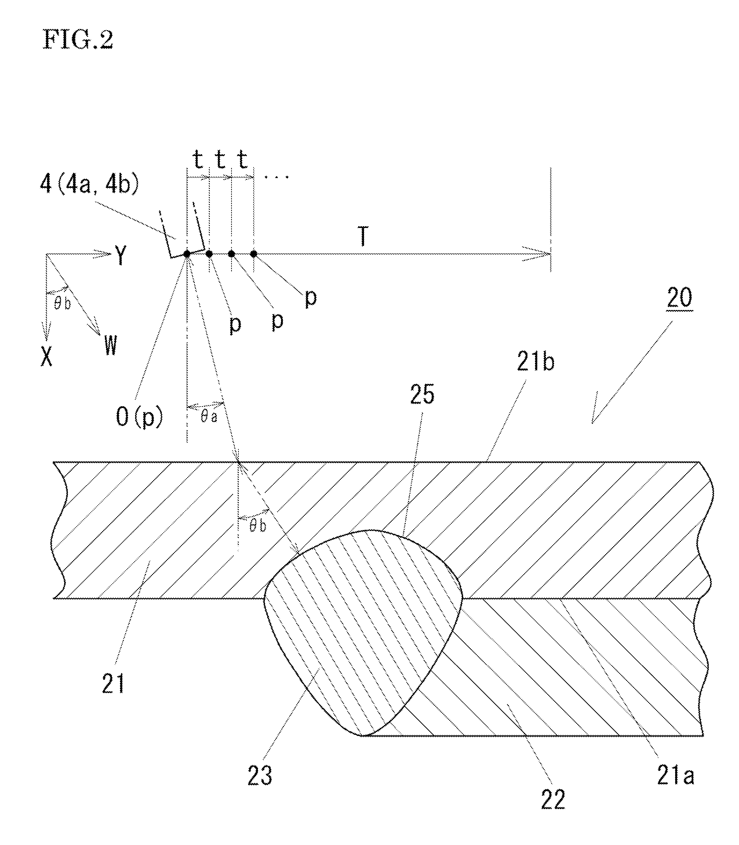
[0027]As described above, the present invention provides an ultrasonic exploration method in which an exploration operation, in which the transmission / reception position, at which ultrasonic waves are transmitted and received, is changed by a specified pitch distance, is performed for each of a plurality of incident angles, a nonlinear image in which echo signals acquired from harmonic waves of reflected waves are presented on the basis of the response time of the ultrasonic waves is generated for each incident angle, each nonlinear image is converted into a frame conversion image in accordance with the cross-sectional shape of an exploration-target area, and frame conversion images formed by only echo signals whose signal intensity is a signal intensity threshold, which is determined for removing echo signals generated by an orientation defect, or more are overlapped to generate a nonlinear exploration image of the exploration-target area. The method is achieved by finding that harmonic waves of reflected waves contain defective reflected waves generated by an orientation defect. According to such a method, echo signals resulting from defective reflected waves mentioned above can be removed using the signal intensity threshold. Therefore, it is possible to stably provide a nonlinear exploration image in which the cross-sectional shape of the exploration-target area is clearly shown by overlapping frame conversion images after the removal. Thus, according to the ultrasonic exploration method of the present invention, it is possible to provide a cross-sectional image of a welded portion of an automobile wheel described above, for example, as a nonlinear exploration image in which the interface shape of the welded portion is accurately presented, allowing easy and accurate inspection of the welded portion.
[0028]In the ultrasonic exploration method described above, in the case where the aspect ratio of the frame of the nonlinear image for each incident angle is corrected in accordance with the number of data prescribed in accordance with the pitch distance and the number of data prescribed in accordance with the refraction angle and the sonic speed of ultrasonic waves and thereafter an angle correction is performed in accordance with the refraction angle to generate a frame conversion image, it is possible to determine position information on echo signals in each frame conversion image by quantitative values (coordinate position data), and to achieve correlation of position information on echo signals between frame conversion images.
[0029]In the ultrasonic exploration method described above, in the case where the size of frame conversion images other than a frame conversion image with the largest number of data is corrected so as to match the frame size of the frame conversion image with the largest number of data before overlapping the frame conversion images, the largest number of data is maintained. Therefore, it is possible to maintain the image processing accuracy while preventing a reduction in number of data. Therefore, a high-precision nonlinear exploration image can be generated by overlapping the frame conversion images after correcting the size of the frame conversion images.
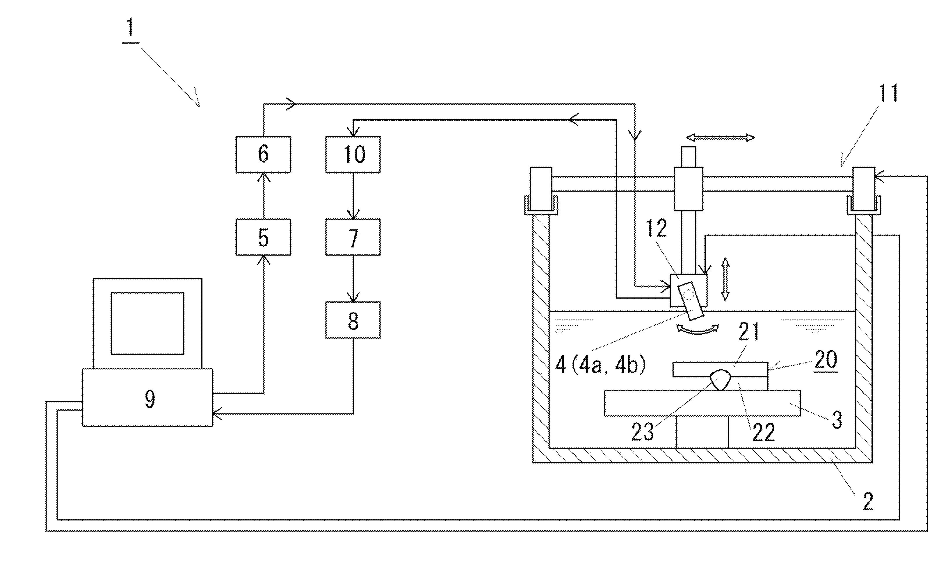
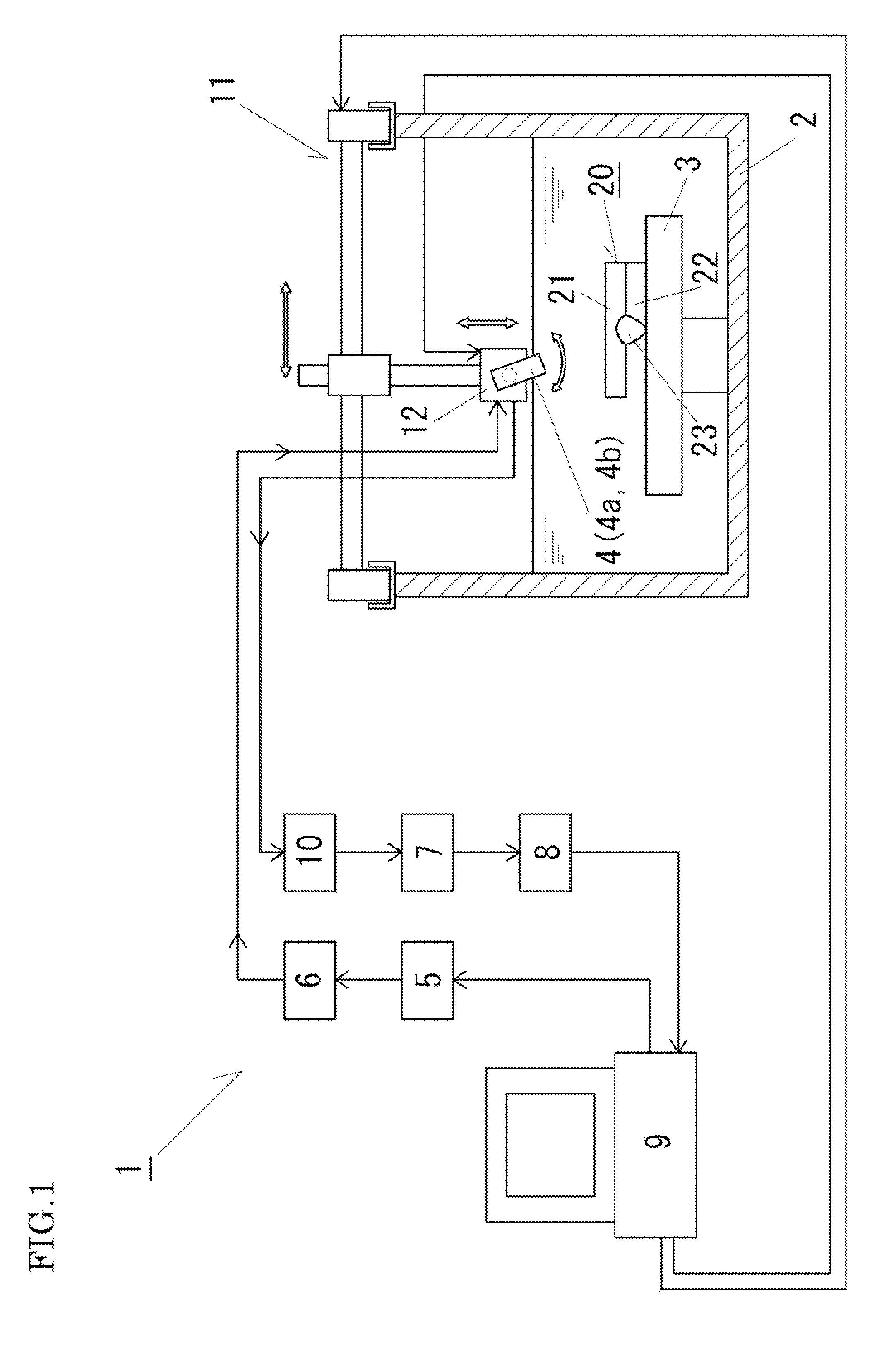
[0030]An ultrasonic exploration apparatus according to the present invention includes ultrasonic wave generation means, a probe including a transmission section and a reception section, probe scanning means for moving the probe, probe tilting means for tilting the probe, scanning control means for controlling operation of the probe scanning means and the probe tilting means so as to perform an exploration operation, in which the probe is moved by a specified pitch distance, for each of a plurality of incident angles. The exploration image processing means according to the present invention generates for each incident angle a nonlinear image in which echo signals acquired from harmonic waves of reflected waves are presented on the basis of the response time of the ultrasonic waves, converting each nonlinear image into a frame conversion image in accordance with the cross-sectional shape of an exploration-target area, and overlapping frame conversion images formed by only echo signals whose signal intensity is a signal intensity threshold, which is determined for removing echo signals generated by an orientation defect, or more to generate a nonlinear exploration image of the exploration-target area. The apparatus is achieved on the basis of the finding that harmonic waves of reflected waves contain defective reflected waves generated by an orientation defect. According to such a configuration, it is possible to stably provide a nonlinear exploration image in which the cross-sectional shape of the exploration-target area is clearly presented in the same way as the method described above. Then, by using the apparatus to the inspection of a welded portion of an automobile wheel described above, for example, it is possible to accurately and stably determine from the nonlinear exploration image whether or not the welded portion is adequate.

Problems solved by technology

In this method, however, the automobile wheel used in the inspection is discarded to increase the production cost in accordance with the proportion of samples.
In addition, this method requires various work to be performed sequentially, such as cutting an automobile wheel, polishing the cut surface, and measuring the actual welding depth, which require a relatively large amount of time and effort.

Method used


Image

  • Ultrasonic exploration method and ultrasonic exploration apparatus
  • Ultrasonic exploration method and ultrasonic exploration apparatus
  • Ultrasonic exploration method and ultrasonic exploration apparatus

Examples


Embodiment Construction

[0040]An embodiment of the present invention will be described in detail with reference to the accompanying drawings.

[0041]FIG. 1 is a schematic diagram of an ultrasonic exploration apparatus 1 according to an embodiment of the present invention. The ultrasonic exploration apparatus 1 includes a water tank 2 provided with a placement table 3 for placement of an exploration-target metal body 20. The exploration-target metal body 20 is placed in water in the water tank 2. The ultrasonic exploration apparatus 1 also includes a probe 4 located in the water in the water tank 2 to transmit specified ultrasonic waves to the exploration-target metal body 20 and receive reflected waves of the ultrasonic waves.

[0042]The ultrasonic exploration apparatus 1 is provided with a probe scanning device 11 that moves the probe 4 described above upward and downward in the vertical direction and forward and rearward and leftward and rightward in the horizontal direction (a mechanism for forward and rear...


PUM


Abstract

To propose an ultrasonic exploration method and an ultrasonic exploration apparatus that allow exploration of an exploration-target area such as a welded portion to provide a cross-sectional image of the exploration-target area accurately and stably.
[Solution] An exploration operation, in which the transmission/reception position, at which ultrasonic waves are transmitted and received, is changed by a specified pitch distance, is performed for each of a plurality of incident angles. A nonlinear image in which echo signals acquired from harmonic waves of reflected waves are presented is generated for each incident angle. Each nonlinear image is converted into a frame conversion image in accordance with the cross-sectional shape of an exploration-target area. A signal intensity threshold for removing echo signals resulting from an orientation defect is determined in advance. Frame conversion images formed by only echo signals 41a whose signal intensity is the signal intensity threshold or more are overlapped to generate a nonlinear exploration image 35. Exploration of a welded portion 23 stably provides a nonlinear exploration image 35 in which the shape of an interface 25 of the welded portion 23 is shown accurately and clearly.

Description

CROSS-REFERENCE TO PRIOR APPLICATIONS[0001]Priority is claimed to Japanese Patent Application No. 2009-081304, filed on Mar. 30, 2009, which is hereby incorporated by reference in its entirety herein.FIELD OF THE INVENTION[0002]The present invention relates to an ultrasonic exploration method and an ultrasonic exploration apparatus that allow non-destructive exploration of an exploration-target metal body formed by, for example, welding metal members to provide an exploration image of a cross-sectional shape of the exploration-target metal body.BACKGROUND[0003]Automobile wheels made of steel, for example, typically have a so-called two-piece structure in which a wheel rim and a wheel disc are welded to each other. It is known that the peripheral edge of a flange portion of the wheel disc and the inner circumferential surface of the wheel rim can be joined with each other by fillet welding. Since the automobile wheels are important safety components, it is desired that the automobile...

Claims


Application Information

Patent Timeline
Patent Type & Authority Applications(United States)
IPC IPC(8): G01S15/00
CPCG01N29/12G01N29/265G01N2291/2696G01N29/348G01N2291/267G01N29/28
Inventor ICHIGO, KAZUYOSHIKAWASHIMA, KOICHIRO
Owner CENTRAL MOTOR WHEEL CO LTD
Why Eureka
Try Eureka