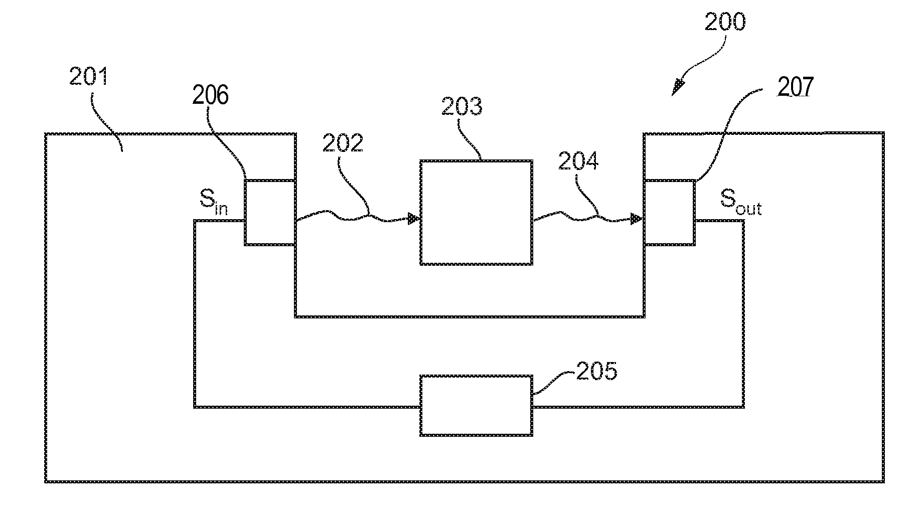
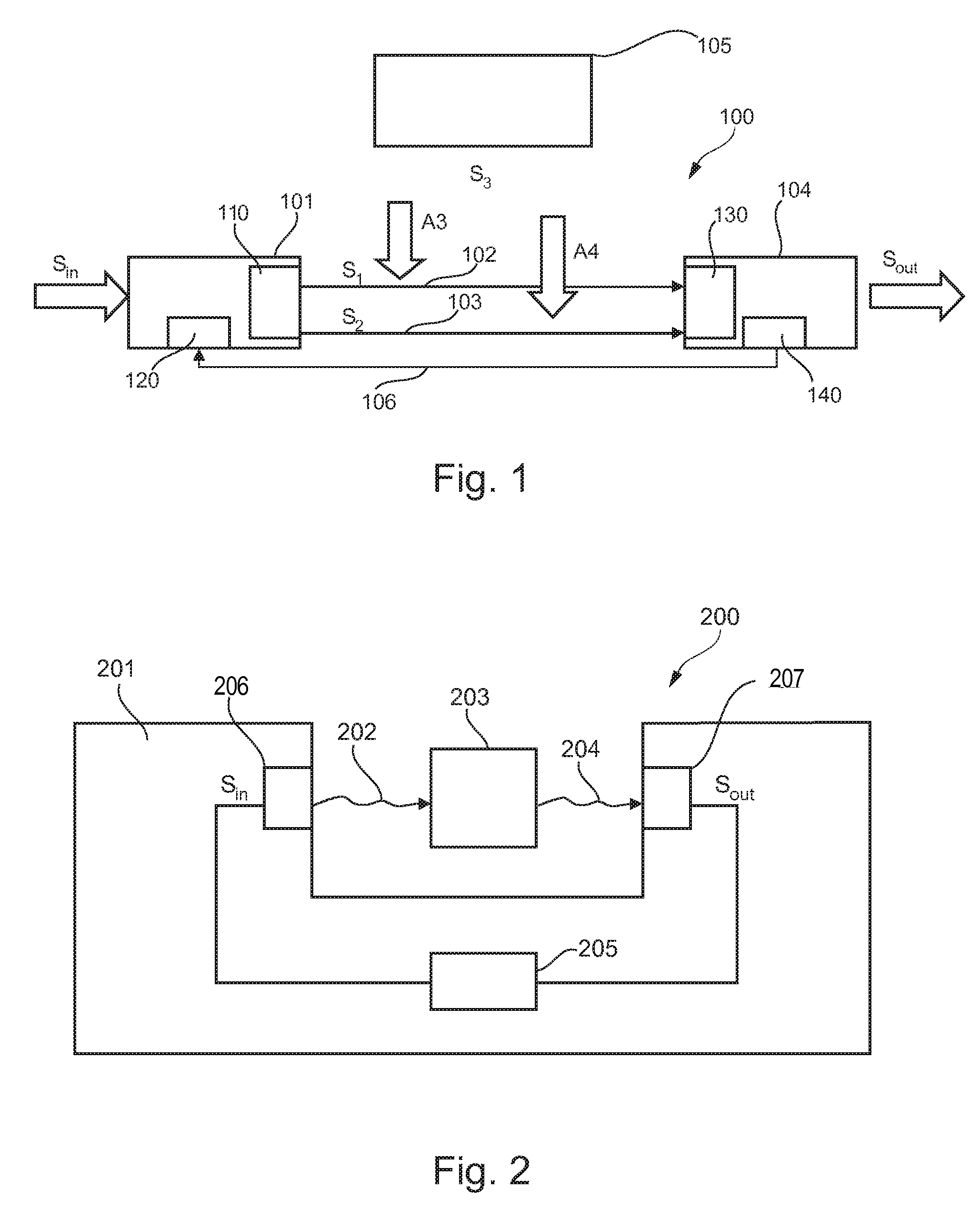
[0017]According to the invention, a system for calibrating a communication arrangement is provided, in which interference signals (or disturbing signals) are efficiently suppressed. In accordance with such a system, a sender is brought into a silent non-transmitting state. In this state, a transfer function of a receiver is adjusted in a manner to reduce an output signal of the receiver originating from interference signals in the environment as much as possible. Subsequently, the transmitter is adjusted in such a way that its transfer function is essentially inverse to the transfer function of the receiver. By doing so, common mode interferences are suppressed and a data transmission with an improved common mode rejection is obtained. Such a system allows for efficient suppression of an influence of interference signals on the signal
transmission line even when multiple transmission paths are used (for instance in a differential data
transmission system). This also holds for a
scenario in which the interference signals couple into the different transmission paths in an unequal or different manner. It should be noted that the
transmission channel can be wire based (for instance via a cable, for example in a similar manner as in a
USB communication), or based on
wireless communication according to a corresponding
wireless data
transmission protocol (for instance using a 13.56 MHz frequency of an RFID system, using a
Bluetooth system, using
infrared communication, etc.). Furthermore, it should be noted that
signal processing and data communication calibration for suppressing interference signals and for improving the
signal quality which is performed according to embodiments of the invention can be realized by a
computer program, that is by
software, or by using one or more special electronic optimization circuits, that is in hardware, or in
hybrid form, that is by means of
software components and hardware components.
[0022]It is advantageous if the method comprises the step of transmitting the signals from the transmitter to the receiver after having adjusted the receiver transfer function and after having set the transmitter transfer function. In other words, first, a calibration phase is performed, in which the receiver transfer function and the transmitter transfer functions are adjusted for an efficient suppression of an influence of interfering signals on the data
transmission line. Subsequently, data communication is performed with proper data
transmission quality.
[0023]It is furthermore advantageous if the method comprises the step of transmitting the signals via a
multi channel (particularly multi-wire) communication from the transmitter to the receiver. For example, the signals are transmitted via two or more wires, for instance in a differential manner. In such a
scenario it may happen that a interference signal couples into the different communication paths in a different manner. The interference signal suppression scheme according to an exemplary embodiment of the invention allows for a proper
transmission quality even under such harsh circumstances.
[0025]Advantageously, the method also comprises the step of adjusting the receiver transfer function by adjusting a plurality of stages of the receiver. For example, the receiver has two input stages, and the transmitter has two output stages. Then, the transfer functions being indicative of the performance of the individual stages are adjusted individually, thereby improving accuracy of the adjustment. First, the sender is muted and then the receiver transfer functions is determined by adjusting the input stages of the receiver (e.g. in
gain and phase) so that the output signal is a minimum. Finally, the sender transfer functions is set to the inverse receiver transfer functions, and the data transmission is started. By taking this measure, a compensation of different interference signals on a
transmission line is possible, thereby particularly enabling improved data transmission via two or more wires.
[0035]According to another exemplary embodiment of the invention, the calibration and data transmission scheme as described hereinbefore is also used for suppressing distortions (like ripples) in a
voltage generated by a
voltage supply unit. By taking this measure,
voltage drops or other distortions may be avoided. Particularly, a voltage
smoothing effect is obtained. The system may be used in amplifiers in order to regulate a signal when signal distortions are measured. In a low-pass filter, a voltage may be smoothed by performing a frequency-dependent suppression of interference signals.

