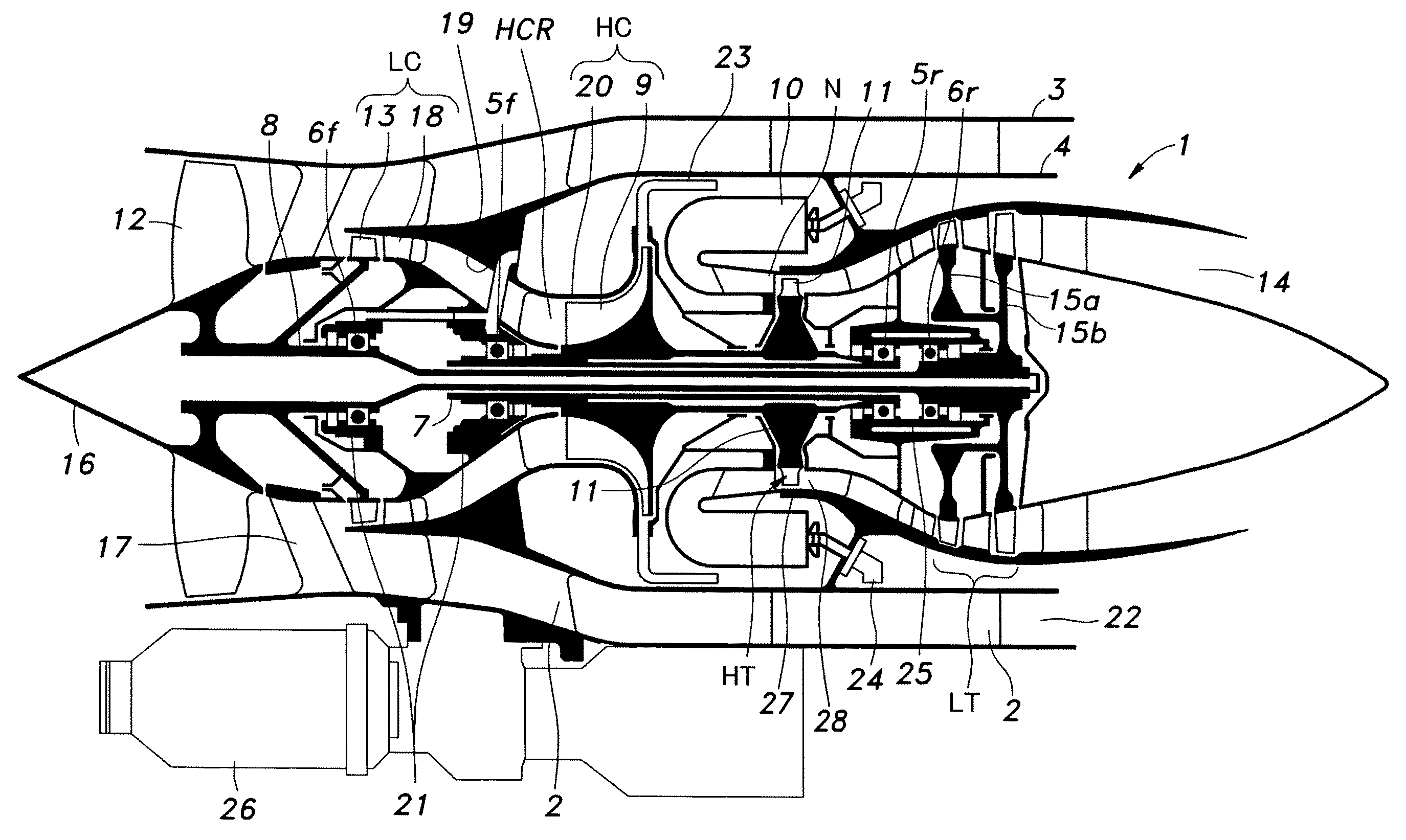

Turbine shroud

a turbine and shroud technology, applied in the direction of liquid fuel engines, machines/engines, mechanical apparatus, etc., can solve the problems of affecting the performance of gas turbine engines, serious fuel economy problems, engine performance drop, etc., and achieve the effect of reducing the thermal stress of each shroud segmen

Active Publication Date: 2010-09-30
HONDA MOTOR CO LTD
View PDF10 Cites 72 Cited by
  • Summary
  • Abstract
  • Description
  • Claims
  • Application Information

AI Technical Summary

Benefits of technology

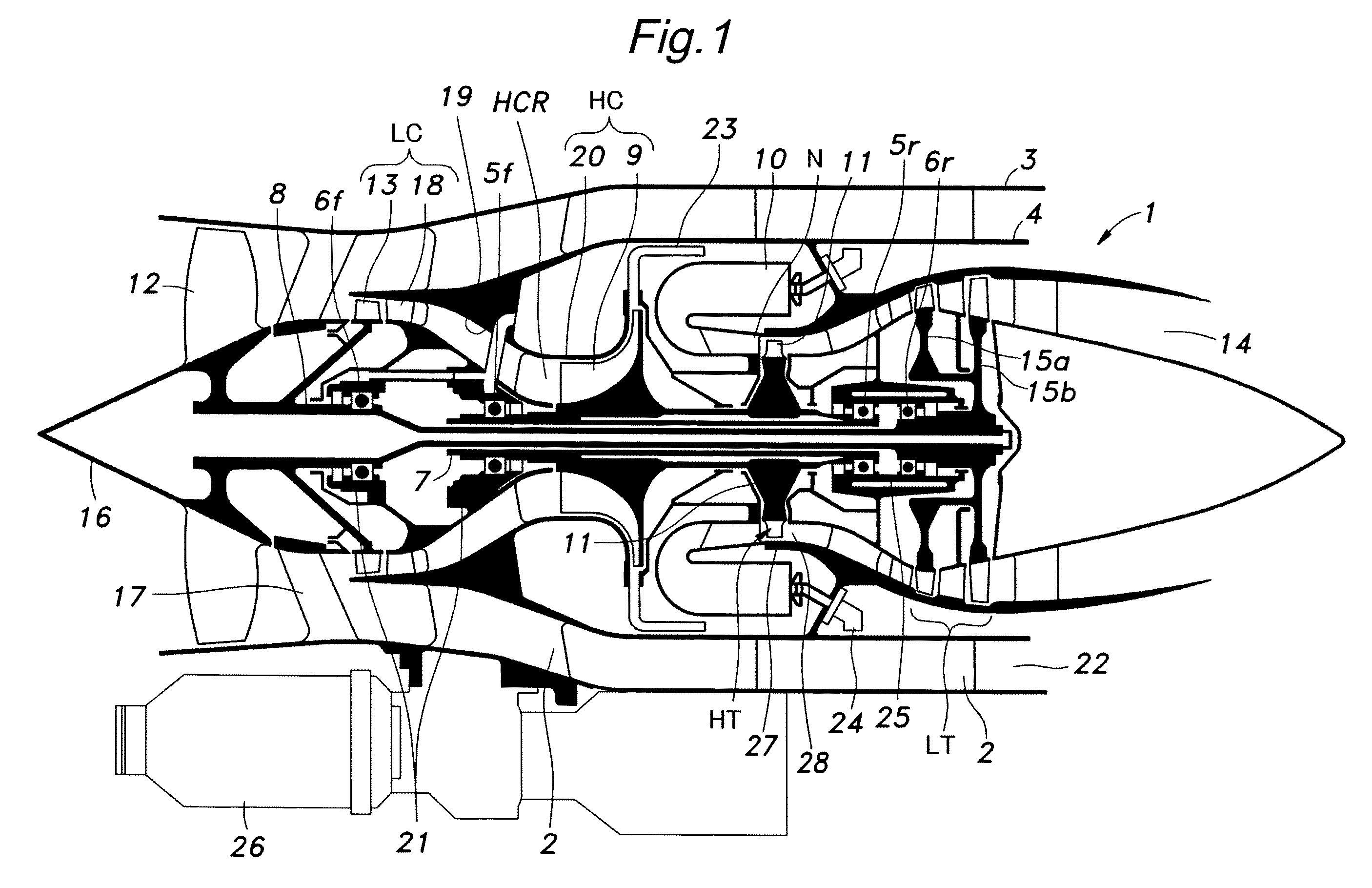
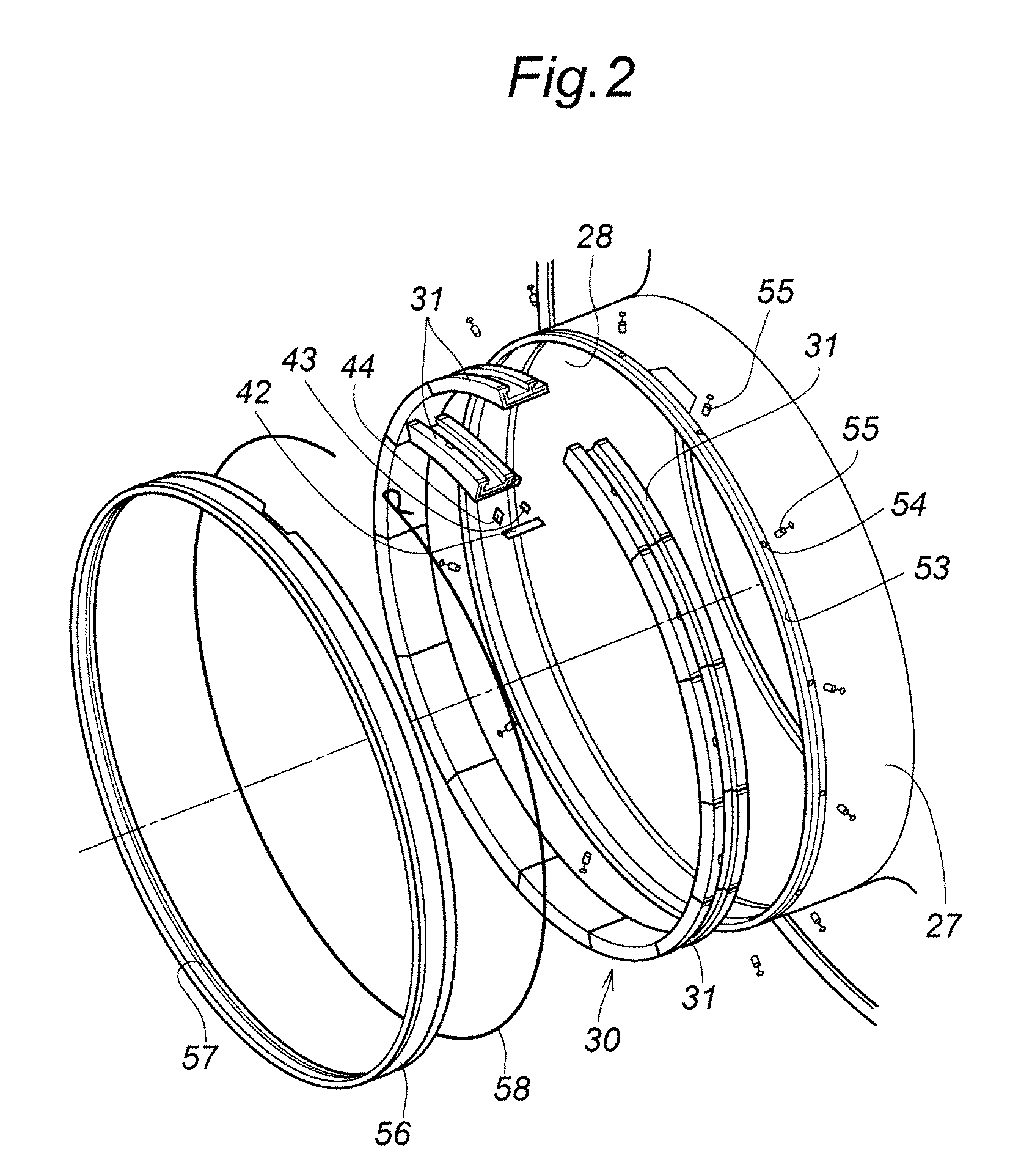
[0006]In view of such problems of the prior art, a primary object of the present invention is to provide a turbine shroud that can minimize leakage of cooling air while avoiding any undue thermal stress in the turbine shroud.
[0007]A second object of the present invention is to provide a turbine shroud formed by combining a plurality of arcuate shroud segments into an annular assembly that can minimize both leakage of cooling air and thermal stress.
[0009]When exposed to the high temperature of combustion gas in the gas turbine engine, a radial temperature gradient develops in each shroud segment, and this causes a warping or deformation of the shroud segment so as to reduce the curvature radius thereof. By defining a clearance between the axial wall and the opposing inner circumferential surface of the turbine casing so as to be greater in each circumferential end part than in a circumferential middle part under a cool condition of the engine, once the engine is warmed up, the clearance can be made substantially uniform over the entire circumference of the shroud segment so that the cooling air leakage can be minimized while minimizing thermal stress that may be caused by the thermal expansion of the shroud segment.
[0013]Preferably, each circumferential end portion of the outer circumferential surface of the axial wall is formed as a slanting surface defining a progressively thinner wall thickness toward a corresponding circumferential edge of the circumferential end portion. This contributes to the minimization of the thermal stress of each shroud segment. According to another embodiment of the present invention, at least one of the outer circumferential surface and inner circumferential surface of the axial wall is defined by a non-cylindrical curved surface.

Problems solved by technology

However, this clearance causes leakage of cooling air from a cooling air chamber defined around the turbine shroud and the opposing surface of the turbine casing into the turbine chamber, and this may impair the performance of the gas turbine engine.
In a gas turbine engine, a slight drop in engine performance means a serious problem for fuel economy.

Method used


Image

  • Turbine shroud
  • Turbine shroud
  • Turbine shroud

Examples


second embodiment

[0063]FIG. 9 shows the present invention. In this embodiment, the inner circumferential surfaces 27A and 27B of the annular axial slots 51 and 52 of the turbine casing 27 opposing the outer circumferential surfaces 33Aa and 34Aa of the front and rear axial walls 33A and 34A, respectively, are defined by cylindrical surfaces centered around the rotational center Xt of the turbine and having radii of Ra and Rb, respectively, and the outer circumferential surfaces 33Aa and 34Aa of the axial walls 33A and 34A are defined by non-cylindrical surfaces such as elliptic and parabolic surfaces that define a greater clearance in each circumferential end than in the circumferential middle part. The outer circumferential surfaces of the axial walls are each additionally formed with a planar sloping surface 45 at each circumferential end thereof.

[0064]In this case also, when the surrounding temperature is low, the clearance is greater in each circumferentially terminal end than in the circumferen...

third embodiment

[0066]FIGS. 10A and 10B show the present invention. In particular, FIG. 10A shows the state of a shroud segment 31 when the engine is cold, and FIG. 10B shows the state of the shroud segment 31 when the engine is warmed up. The shroud segment 31 is configured such that, when the engine is cold, the clearance Cc, Cd between the inner circumferential surface 33Ab, 34Ab of each axial wall 33A, 34A and opposing outer circumferential surface 27C, 27D of the annular axial slot 51, 52 is greater in a circumferential middle part M thereof than each circumferential end part thereof E.

[0067]In this case, whereas the outer circumferential surface 33Aa, 34Aa of each axial wall 33A, 34A consists of a cylindrical surface centered around the rotation center Xt of the turbines, the inner circumferential surface 33Ab, 34Ab of the axial wall 33A, 34A is centered around an axial center offset from the rotation center Xt of the turbines, and is given with a smaller curvature radius. The outer circumfer...

fourth embodiment

[0070]FIGS. 11A and 11B show the present invention. In particular, FIG. 11A shows the state of a shroud segment 31 when the engine is cold, and FIG. 11B shows the state of the shroud segment 31 when the engine is warmed up. The shroud segment 31 is configured such that, when the engine is cold, the clearance Cc, Cd between the inner circumferential surface 33Ab, 34Ab of each axial wall 33A, 34A and opposing outer circumferential surface 27C, 27D of the annular axial slot 51, 52 is greater in a circumferential middle part M thereof than in each circumferential end part thereof E, and, additionally, the clearance Ca, Cb between the outer circumferential surface 33Aa, 34Aa of each axial wall 33A, 34A and opposing inner circumferential surface 27A, 27B of the annular axial slot 51, 52 is greater in each circumferential end part thereof E than in a circumferential middle part M thereof.

[0071]In this case also, when the engine is warmed up, the thermal deformation of the shroud segment 31...


PUM


Abstract

A turbine shroud (30) of a gas turbine engine comprises a plurality of arcuate shroud segments (31) combined into an annular configuration, each shroud segment including a main body (32) defining an inner circumferential surface opposing the tips of the turbine rotor blades (11a) at a small clearance and an engagement feature including an axial wall (33a, 34a) having a prescribed circumferential length and a prescribed axial length, the turbine casing including an axial slot (51, 52) extending coaxially around the center line of the engine and configured to receive the axially extending wall of each shroud segment. A clearance defined between each circumferential end part (E) of the axial wall and an opposing inner circumferential surface of the turbine casing is greater than that defined between a circumferentially middle part (M) of the axial wall and an opposing inner circumferential surface of the turbine casing under a cool condition of the engine. A radial temperature gradient that develops in each shroud segment when the engine is warmed causes a deformation of the shroud segment such that the clearance can be made substantially uniform over the entire circumference of the shroud segment and the cooling air leakage can be minimized while minimizing thermal stress that may be caused by the thermal expansion of the shroud segment.

Description

TECHNICAL FIELD[0001]The present invention relates to a turbine shroud, and in particular to a turbine shroud that surrounds turbine rotor blades of a gas turbine engine and defines an annular cooling fluid chamber.BACKGROUND OF THE INVENTION[0002]A high pressure turbine of a gas turbine engine is surrounded by an annular turbine shroud, and a small annular gap is defined between the outer tips of the turbine rotor blades and the opposing inner circumferential surface of the turbine shroud. Typically, a turbine shroud is formed by a plurality of arcuate shroud segments combined into an annular assembly, and attached to an inner peripheral wall of a turbine casing. See Japanese patent laid open publication No. 4-330302 and Japanese patent laid open publication No. 2000-54804, for instance.[0003]A turbine shroud is exposed to combustion gas of a high temperature, and this causes a temperature gradient in a radial direction. The temperature gradient in turn causes an uneven thermal exp...

Claims


Application Information

Patent Timeline
IPC IPC(8): F01D11/08
CPCF01D11/18F01D25/246F05D2230/642F05D2240/57F05D2240/11
Inventor NAKAMURA, ORIOURA, YOSHIYUKI
Owner HONDA MOTOR CO LTD
Learn More