Pci.express communication system and communication method thereof

a communication system and express technology, applied in the field of pci.express communication system and communication method thereof, can solve the problems of recovering data error of address, affecting so as to improve the fault tolerance of pci.express, shorten the fault recovery time, and improve the effect of fault toleran

Inactive Publication Date: 2010-09-30
KK TOSHIBA
View PDF7 Cites 28 Cited by
  • Summary
  • Abstract
  • Description
  • Claims
  • Application Information

AI Technical Summary

Benefits of technology

[0066]aforementioned receiving device performs return transmission of second requested data in respect of aforementioned memory read request; and aforementioned transmission device terminates this transaction on receiving aforementioned requested data after overwriting with the second data aforementioned first data error location that was held; whereby, by means of aforementioned error information, improvement in the fault tolerance on error generation and a shortening of the fault recovery time are made possible.
[0067]According to the present invention, an improvement in fault tolerance of a PCI.Express communication system can be achieved in respect of irrecoverable faults of a specified region in the data buffer in a relay device or end device of the PCI.Express communication system, or in respect of transient software errors, and a PCI.Express communication system and communication method therefore can be provided in which the fault recovery time can be shortened.

Problems solved by technology

This delay may become even larger in the case of a system in which the switch 2 has a large number of endpoints connected thereto.
Also, there is the problem that, in cases where the endpoint 3c is constituted as a device that operates in a standby fashion with regard to the endpoint 3a, in cases where changeover of the device is triggered by this error message TLP3, such delay in the changeover time represents a period of malfunction of the system.
In this case, there is the problem that, if the buffer address CF4 h is permanently faulty, writing the same data to the same region of the data buffer 3a2 will not result in recovery of the data error of the address CF4 h.
This has the problem that a long time is required to complete transmission.
Another method is to duplicate the data buffer 3a3, using each data buffer alternately: however, this involves increased memory costs.
However, as stated in patent reference 1, if reliability of the relay device is sufficiently guaranteed and if a data error detection function, such as for example parity in the transmission and reception data buffer, is provided in the transaction layer, guarantee of end-to-end data integrity can be achieved by supplementation by the LCRC, so it may be concluded that the ECRC is unnecessary.
However, if a PCI.Express communication system is constructed in which the reserve bit is utilized with this objective, if, in future, the PCI.Express standard is revised so that a new definition is allocated to this reserve bit, it is possible that compatibility with the future PCI.Express standard will be lost.
As described above, in regard to TLP transactions based on the conventional PCI.Express specification, there are problems concerning time for fault recovery in the event of an error and concerning fault-tolerance.

Method used


Image

  • Pci.express communication system and communication method thereof
  • Pci.express communication system and communication method thereof
  • Pci.express communication system and communication method thereof

Examples


embodiment 1

[0079]FIG. 6 shows an example of the format of a TLP digest according to the present invention and FIG. 7 shows a layout diagram given in explanation of an example of the operation of the PCI.Express communication system employing this TLP digest.

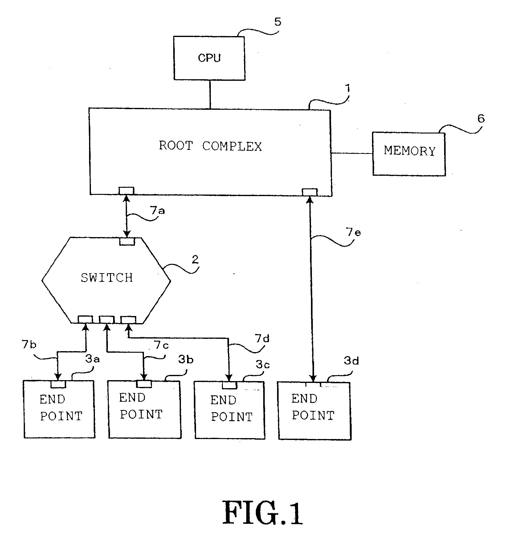
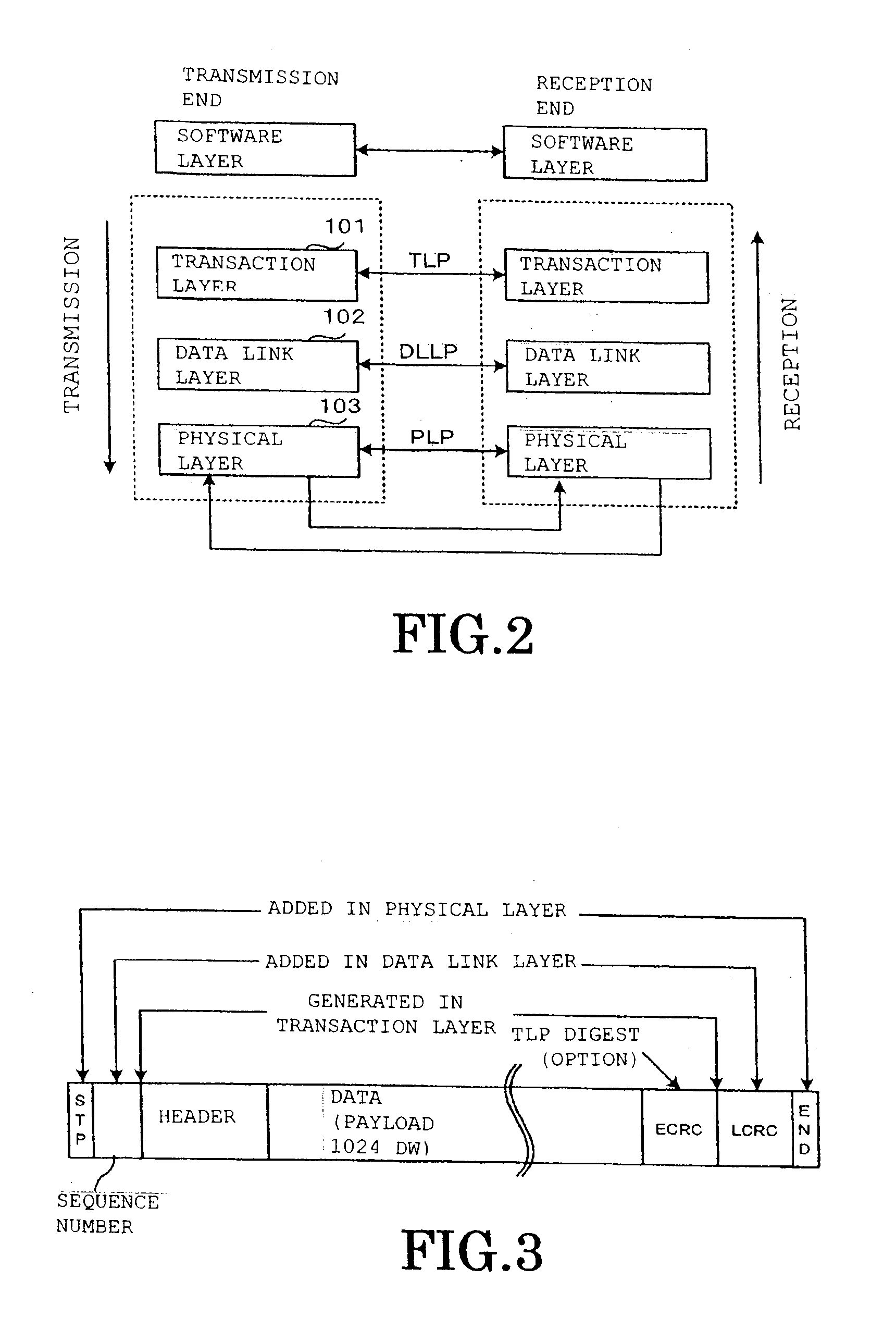
[0080]The various parts of this embodiment 1 are given the same reference numbers as corresponding parts in the PCI.Express communication system of the prior art example shown in FIG. 1 to FIG. 5, and further description thereof is dispensed with.

[0081]The points of difference between the embodiment of the present invention of FIG. 6 and the prior art PCI.Express communication system example described in FIG. 5 are that, whereas, in the conventional PCI.Express communication system in which a cut-through transmission system is adopted, when an error is detected in the untransmitted data during transmission of a TLP at the endpoint 3a, typically the method is adopted that the ECRC is inverted and the packet is nullified (nullified TLP) by ch...

embodiment 2

[0129]Next, a method of communication in a PCI.Express communication system wherein PCI.Express devices (hereinbelow called customized devices) in which the TLP digest is independently employed, as described in embodiment 1, and conventional PCI.Express devices (hereinbelow called conventional devices or universal devices) are both present will be described.

[0130]If all the PCI.Express devices in the PCI.Express communication system are designed with independence, all of the devices may suitably be designed so as to be capable of setting / detection of error information as described in embodiment 1 in the TLP digest.

[0131]However, even in the case of PCI.Express communication systems for industrial purposes, in which reliability is required, the case may be considered in which the construction of the PCI.Express communication system that is adopted includes both conventional devices and customized devices designed with independence as illustrated in embodiment 1.

[0132]For example, as ...


PUM


Abstract

When a transaction layer circuit detects an error, error information in respect of transmission data is set in a TLP digest. The method includes: a step in which, at an endpoint (3a) that receives a memory read request transmitted by the root complex 1, if an error is detected during transmission of first data corresponding to the requested TLP, error information is set in the TLP digest and a completion with data attached is returned; a step in which the root complex (1) returns a memory read request based on the error information to the endpoint; a step in which the endpoint returns requested second data; and a step in which the root complex terminates the response after overwriting the error location of the first data that was held, with the second data.

Description

CROSS-REFERENCE TO RELATED APPLICATION[0001]This application claims benefit of priority from Japanese application number JP 2009-87994 filed Mar. 31, 2009, the entire contents of which are incorporated by reference herein.BACKGROUND OF THE INVENTION[0002]1. Field of the Invention[0003]The present invention relates to a PCI.Express communication system and communication method thereof and in particular relates to improvements in the transmission protocol of the transaction layer packets (TLP) on error generation.[0004]2. Description of the Related Art[0005]A “PCI.Express” (registered trademark) bus is a type of high-speed serial interface using a point-to-point connection that has been developed in recent years for transmission of data in computer systems and other electronic devices. Such a serial interface bus occupies less area on the circuit board than conventional parallel transmission and so makes possible further miniaturization: its application is being studied in many fields...

Claims


Application Information

Patent Timeline
Patent Type & Authority Applications(United States)
IPC IPC(8): H04L1/18
CPCG06F13/4282
Inventor MURAKAMI, MASAYUKITAKEHARA, JUNARAMAKI, NARUHIKOKAWAMURA, TOSHIKAZUTAKAYANAGI, YOICHIOKABE, MOTOHIKO
Owner KK TOSHIBA
Why Eureka
Try Eureka