Method and Apparatus for Characterizing a Sample with Two or More Optical Traps

Active Publication Date: 2010-09-30
JPK INSTR
View PDF3 Cites 25 Cited by
  • Summary
  • Abstract
  • Description
  • Claims
  • Application Information

AI Technical Summary

Benefits of technology

[0020]In one possible embodiment of the invention it may be provided that a probe carries out a measurement, such as for example the plotting of a topography, and a second probe carries out a different measurement, such as for example a chemical mapping. According to one embodiment of the invention, this may be realised by means of different probes. In this way, it is possible to separate the topography from the chemical measurement. For example, if there are bonding sites on a cell, these would not be detectable without the knowledge of the topography in particular including any interference. By using two or more traps it is ensured here that the time difference bet

Problems solved by technology

As discussed in connection with the prior art, there will inevitably be interferences in the measur

Method used


Image

  • Method and Apparatus for Characterizing a Sample with Two or More Optical Traps
  • Method and Apparatus for Characterizing a Sample with Two or More Optical Traps
  • Method and Apparatus for Characterizing a Sample with Two or More Optical Traps

Examples


Embodiment Construction

[0035]The invention will be explained below by means of preferred embodiments in connection with the attached figures, wherein:

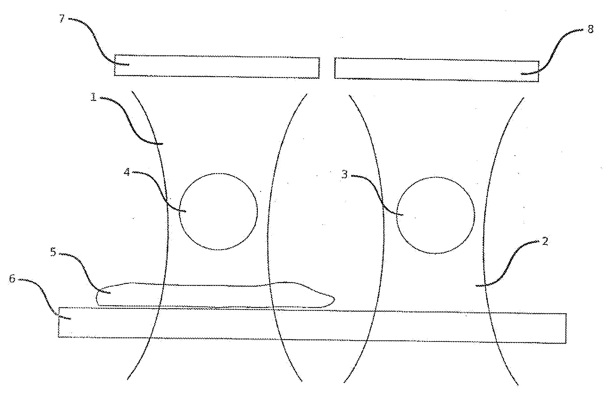
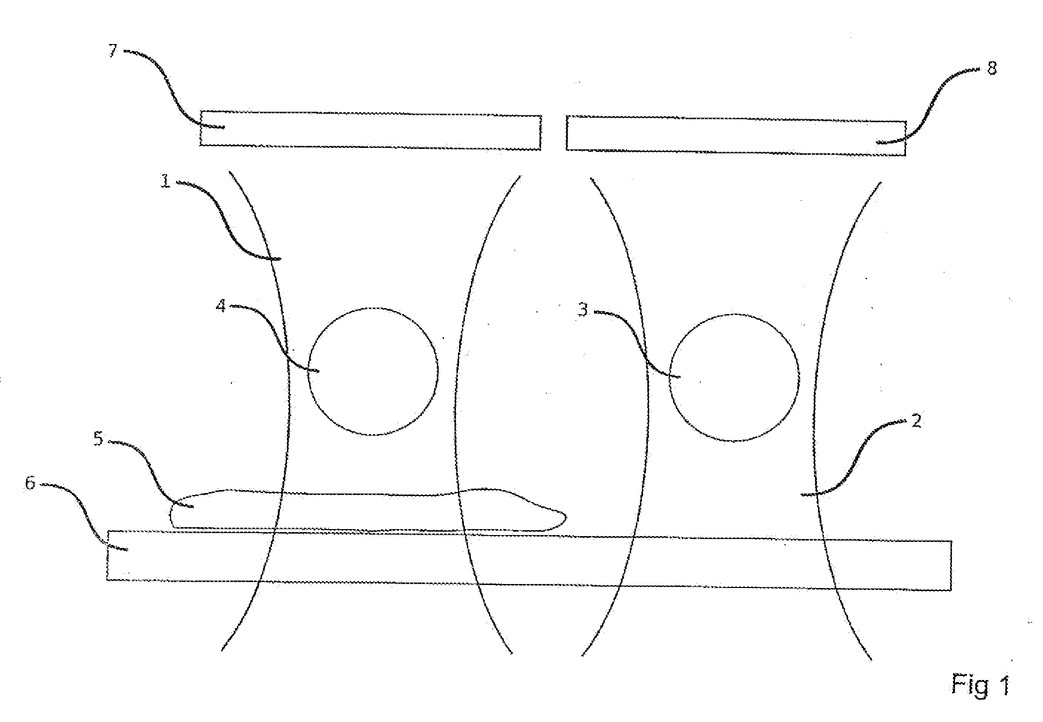
[0036]FIG. 1 shows a simplified illustration of two optical traps including a possible interference on the optical path;

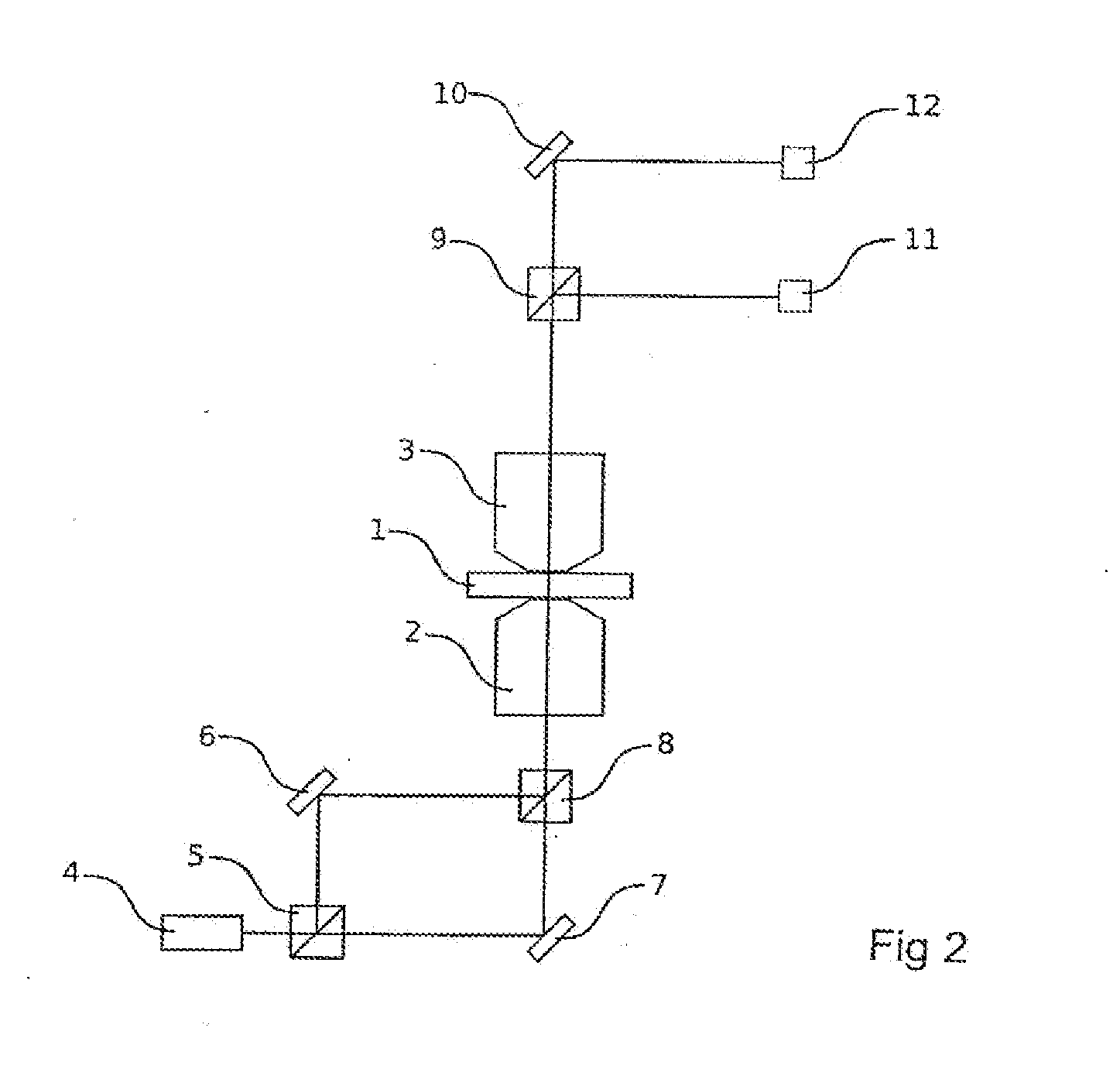
[0037]FIG. 2 shows a schematic diagram of the generation of two traps which distinguish themselves in the polarisation of the light and the separation of the signals of the two traps;

[0038]FIG. 3 shows a schematic diagram of the generation of two traps which distinguish themselves in the wavelength of the light and the separation of the signals of the two traps;

[0039]FIG. 4 shows a schematic diagram of the generation of two traps which distinguish themselves at least in their direction of propagation and the spatially separated detection of the two signals;

[0040]FIGS. 5a and b show a schematic diagram for possible coupled movements of two traps;

[0041]FIG. 6 shows a schematic diagram for possible coupled movements of two or more traps.

[0042]...


PUM


Abstract

The present invention relates to a method for investigating a sample using scanning probe photon microscopy or optical force microscopy, and to an apparatus which is designed accordingly. The method or the apparatus provides for two optical traps which can be moved in a local region of the sample, wherein in at least one of the two traps a probe is held. The sample is scanned using the two traps and the measured data from the two traps are captured separately and evaluated by correlation. In particular interference signals resulting from an interaction between sample and light trap can be eliminated by the method.

Description

[0001]The invention relates to a method and an apparatus for measuring the properties of a sample by means of a scanning probe method, in particular by means of a “Photonic three microscope” (PFM).BACKGROUND OF THE INVENTION[0002]PFM is a scanning probe method, wherein the probe is represented by a particle or a plurality of particles captured in an optical trap. In this case, the optical trap fulfils the role of the cantilever as it is known from the area of scanning force microscopy. Here, the position of the optical trap may be modified by movable or modifiable optical elements in the optical path (acousto-optical deflectors (AOD), galvanically suspended mirrors, spatial light modulators (SLM), piezo-electrically suspended mirrors). Moreover, the position of a captured particle or of a plurality of captured particles may be determined by means of a detection system. In this respect, in principle two methods are distinguished. In the area of Back Focal Plane Interferometry, the in...

Claims


Application Information

Patent Timeline
IPC IPC(8): G01Q10/00G01Q20/00G01N23/00G01Q10/06G01Q30/06G01Q60/00
CPCB82Y35/00G01Q10/06G02B21/32G01Q60/00G01Q30/06
Inventor HEYN, SVEN-PETERKERSSEMAKERS, JACOBKNEBEL, DETLEFEGGERT, HELGEJAEHNKE, TORSTENKAMPS, JOERN
Owner JPK INSTR
Why Eureka
Try Eureka