Braking device and method for elevator drive

a technology of braking device and elevator drive, which is applied in the direction of elevators, hoisting equipment, instruments, etc., can solve problems such as safety hazards, and achieve the effect of increasing braking for

Active Publication Date: 2010-10-07
INVENTIO AG
View PDF13 Cites 10 Cited by
  • Summary
  • Abstract
  • Description
  • Claims
  • Application Information

AI Technical Summary

Benefits of technology

[0031]An advantage of the invention arises through the use of an expedient monitoring logic system which monitors correct functioning of the brake device. This monitoring logic system comprises the sensor device for detecting the normal and / or braking position of the relative element, a speed and / or travel measuring device and the control signal for the brake device. On occasion, the brake device can also be provided with a further sensor for ascertaining the state “contact play removed” or “brake applied” or “contact play present” or “brake released”. In the following a “control signal brake” signals the command state which a control device gives to the brake device as control signal (“apply” or “release”). The “speed” corresponds with the state of the movable element or the travel body or elevator car and indicates whether the movable element is disposed at standstill (0) or in motion (≠0).
[0032]A diagnosis of the state can then follow, for example, the following diagram:
[0033]This diagnostic diagram allows an almost constant monitoring of the function of the brake device, particularly since at each stop (F1, F2) the desired state can be detected and in the event of deviation appropriate measures can be undertaken. No risk exists, since on reaching the braking position an increased braking force, usually a braking force increased by approximately the factor 2, is available. Secure holding is thus guaranteed.
[0034]Equally, on determination of a release fault (F5) the installation can be stopped and the function verified. On the basis of a fault history, which is stored in the monitoring logic system, servicing can be performed in targeted manner.
[0035]A free-running travel of the relative element can in that case be kept small. It can be selected to be merely of such size that reliable determination of the position of the relative element by the sensor device is made possible in simple manner and, on the other hand, no risky deviation in holding such as, for example, formation of a step in the case of an elevator car arises due to the resulting displacement of the movable element or of the travel body. The selected free-running travel is typically approximately 3 to 10 millimeters in each of two directions of movement in correspondence with the first degree of freedom.
[0036]The relative element is kept in its normal position, or returned again to the normal position after relative displacement has taken place, by means of a bias. This bias can be produced by means of, for example, a resilient spring, for example a simple torsion bar, a mechanical torsion spring or helical spring, or also a hydraulic spring. Biasing by means of magnetic force is also possible, in that magnetic poles are appropriately arranged. In the case of use, in particular, of a pressing spring instead of the actuating element as explained in the foregoing, the biasing device can be combined with a magnetic release unit.

Problems solved by technology

This jeopardises safety.

Method used


Image

  • Braking device and method for elevator drive
  • Braking device and method for elevator drive
  • Braking device and method for elevator drive

Examples


Embodiment Construction

[0077]The same reference numerals are used in the figures for equivalent functions.

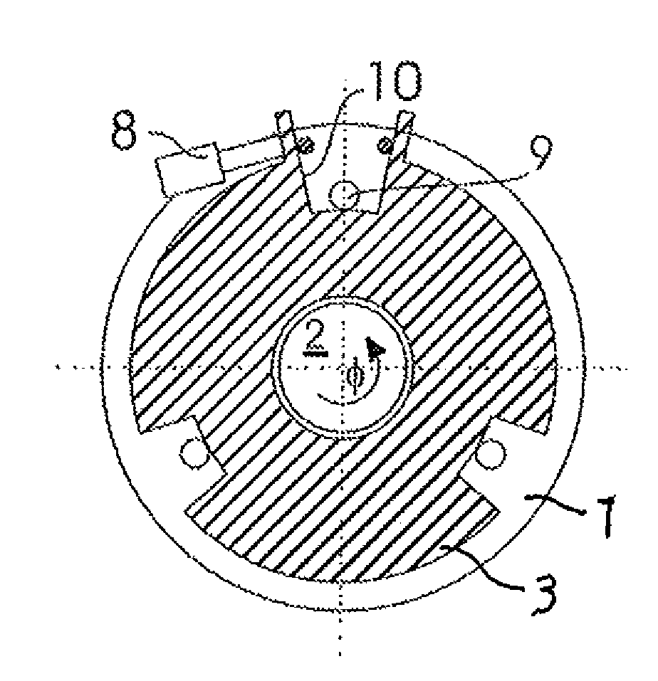
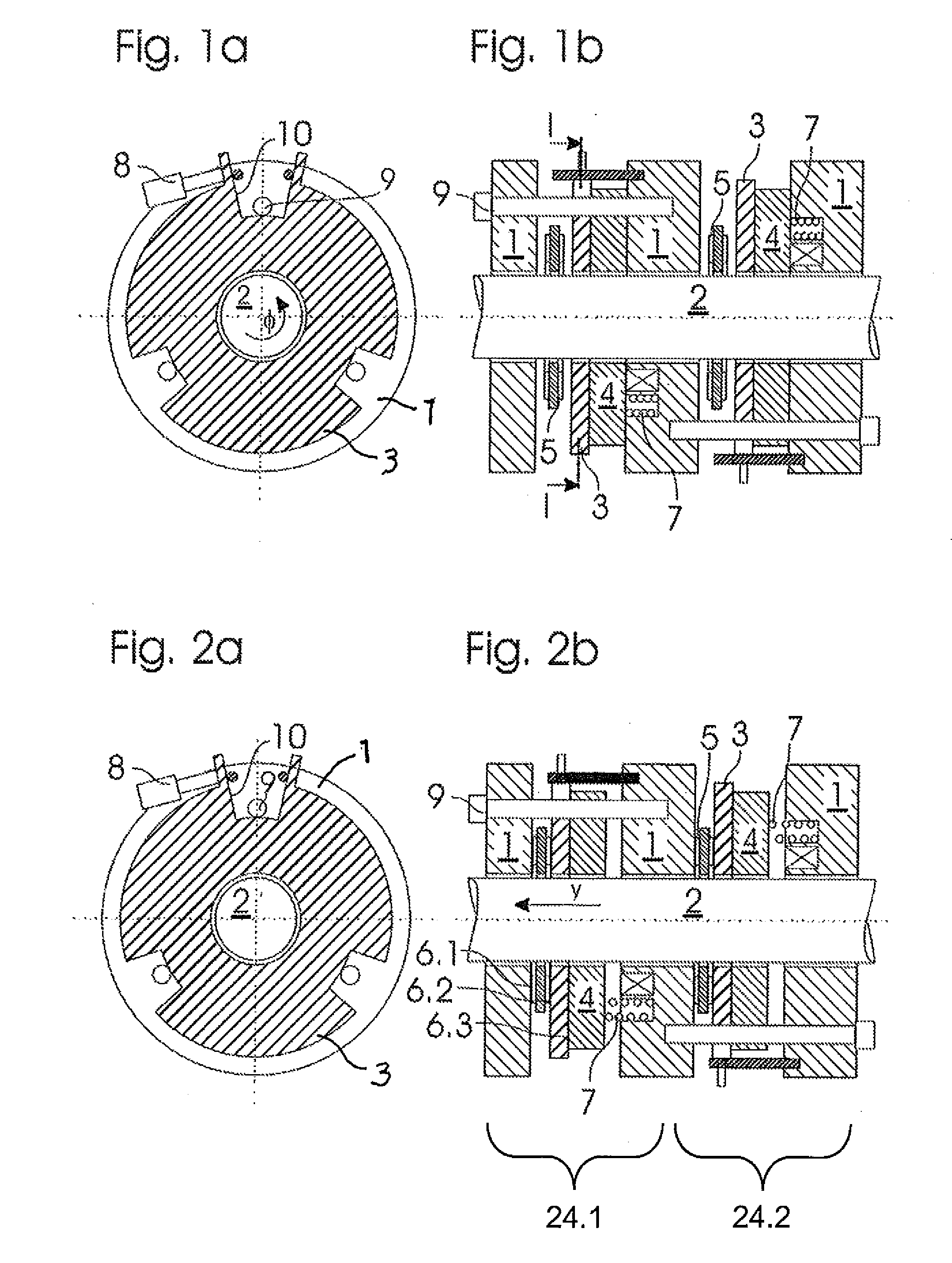
[0078]FIGS. 1a, 1b show a brake device such as is usable for an elevator drive, according to an embodiment of the present invention, in released, non-braking state in a side view and a front view, respectively. The brake device comprises a static element in the form of a multi-part housing 1 which is fixed in terms of inertia. A movable element in the form of an operating shaft 2 is rotatably mounted in the housing 1 and has the degree of rotational freedom φ relative to the housing 1. Two brake elements in the form of brake discs 5 are arranged on the shaft to be axially displaceable, but secure against relative rotation, for example by means of shaft splines or a key (not illustrated).

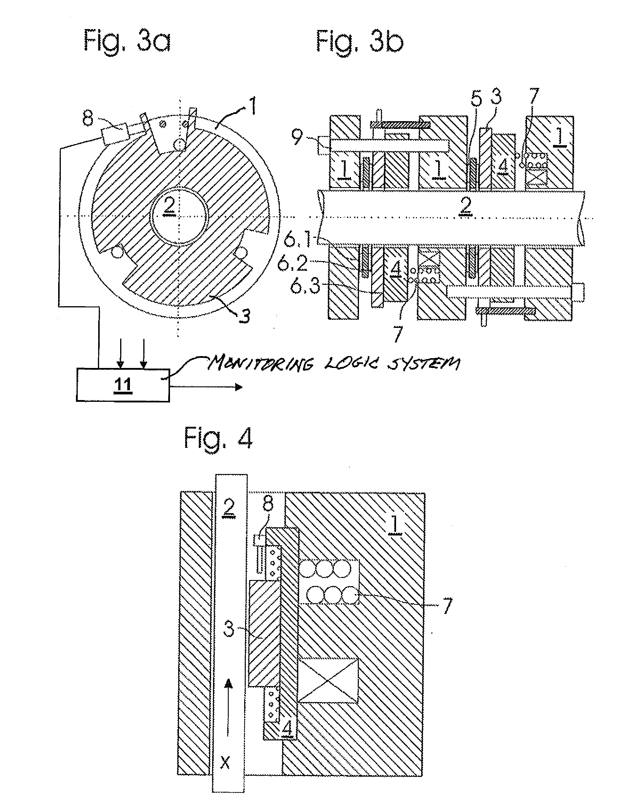
[0079]Two actuating elements in the form of armature discs 4 are mounted in the housing 1 to be axially displaceable, but secure against relative rotation. For this purpose distributed over the circumference are three ...


PUM


Abstract

An elevator drive for driving and detaining an elevator car includes a traction wheel transmitting a driving or detaining force to an elevator car, a motor driving the traction wheel, a braking arrangement for detaining the traction wheel, and a drive shaft connecting the traction wheel, the motor and the braking arrangement. The braking arrangement contains at least two braking devices with the traction wheel arranged between to divide the braking torques transmitted by the traction wheel to the braking devices. Symmetrical division of the braking devices on either side of the traction wheel reduces by half the torque transmitted in the drive shaft. A risk of failure or breakage of the drive shaft is thereby significantly reduced and during a failure of the drive shaft, the braking function continues since the braking devices are distributed on both sides of the traction wheel.

Description

FIELD OF THE INVENTION[0001]The present invention relates to an elevator drive for driving and holding an elevator car, as well as a brake device, a corresponding method and an elevator installation.BACKGROUND OF THE INVENTION[0002]An electromagnetically actuable brake device, such as can be used in an elevator drive, with a stationary housing and a drive shaft rotatable therein is known from DE 197 37 485 C1. Two brake discs are connected with the drive shaft to be secure against rotation relative thereto, but are axially displaceable. Axially displaceable armature discs are each biased, through a respective spring, by a normal force against the brake discs in such a manner that a first frictional contact between the brake discs and the housing and a second frictional contact between the armature discs, which are secure against rotation relative to the housing, and the brake disc are formed. The frictional forces acting in these contacts oppose a rotation between the brake disc, wh...

Claims


Application Information

Patent Timeline
Patent Type & Authority Applications(United States)
IPC IPC(8): B66B1/28B66B11/04B66B1/36F16D55/02F16D65/34F16D65/28
CPCB66B11/043B66D5/14B66B19/007F16D2121/22F16D2123/00F16D2066/003B66B5/18F16D55/24F16D65/14
Inventor FISCHER, DANIEL
Owner INVENTIO AG
Why Eureka
Try Eureka