Vehicular headlamp

a headlamp and headlamp technology, applied in the manufacture of electric discharge tubes/lamps, electrode systems, lighting and heating apparatuses, etc., can solve the problems of cumbersome work, difficult to effectively cool both the light-emitting element and the lighting circuit, and a more complex structure inside the lamp chamber. , to achieve the effect of reducing luminous efficiency, simple internal lamp chamber structure, and avoiding troubles

Inactive Publication Date: 2010-10-07
KOITO MFG CO LTD
View PDF6 Cites 70 Cited by
  • Summary
  • Abstract
  • Description
  • Claims
  • Application Information

AI Technical Summary

Benefits of technology

[0029]In the vehicular headlamp of one or more embodiments, the lighting circuit does not protrude to outside of the lamp chamber. Therefore, the external lamp shape can be made more compact and there is no need to arrange a lead inside the lamp chamber for connecting the light-emitting element and the lighting circuit. Thus, a simple internal lamp chamber structure can be achieved.
[0030]The light-emitting element and the lighting circuit are both cooled by blown air generated by the blowing means. Therefore, it is possible to avoid troubles caused by the light-emitting element generating heat, such as reduced luminous efficiency due to the heat generated by the light-emitting element, variations in the color of light emitted, and failures of electronic components structuring the lighting circuit due to the heat generated by the light-emitting element.
[0031]In particular, the direction, strength, and amount of effective blown air generated by the blowing means for cooling the light-emitting element and the lighting circuit is maintained constant regardless of aiming, and a constant heat release effect is secured for the light-emitting element and the lighting circuit. As a consequence, it is possible to reliably avoid troubles caused by the light-emitting element generating heat.
[0032]According to one or more embodiments, the light-emitting element and the lighting circuit are effectively cooled when blown air generated by the blowing means flows along the ventilation passage between the lighting circuit and the metal heat transfer member. Therefore, any trouble due to heat generated by the light-emitting element can be avoided.
[0033]According to one or more embodiments, the transfer of heat generated by the light-emitting element to the lighting circuit is prevented by the side wall (non-heat transfer member) interposed between the metal heat transfer member and the lighting circuit. In addition, blown air guided to the ventilation passage flows directly inside the ventilation passage without spreading. Therefore, the light-emitting element and the lighting circuit can be effectively cooled, and any trouble in the lighting circuit due to heat generated by the light-emitting element can be avoided. In particular, circulating air convection that is generated around the light source unit guides fresh below the light source unit into the ventilation passage. Therefore, the light-emitting element and the lighting circuit are more effectively cooled, and troubles in the lighting circuit due to heat generated by the light-emitting element can be reliably avoided.
[0034]According to one or more embodiments, the amount of heat released from the metal heat transfer member increases by an amount corresponding to the heat released by the heat radiation fin. Therefore, the light-emitting element is even more effectively cooled, and the cooling effect on the light-emitting element and the lighting circuit due to blown air flowing through the ventilation passage is further increased, which can further prevent any trouble due to heat generated by the light-emitting element.

Problems solved by technology

In addition, the light-emitting element inside the lamp chamber must be connected by a lead to the lighting circuit outside the lamp chamber and this requires cumbersome work.
Such an arrangement contributes to a more complex structure inside the lamp chamber.
However, it is difficult to effectively cool both the light-emitting element and the lighting circuit integratedly attached to the metal heat transfer member by simply providing a blast fan at a predetermined position on the inner side of the lamp body as in Patent Document 1.

Method used


Image

  • Vehicular headlamp
  • Vehicular headlamp
  • Vehicular headlamp

Examples


Embodiment Construction

[0040]Hereinafter, embodiments of the invention will be described with reference to the drawings.

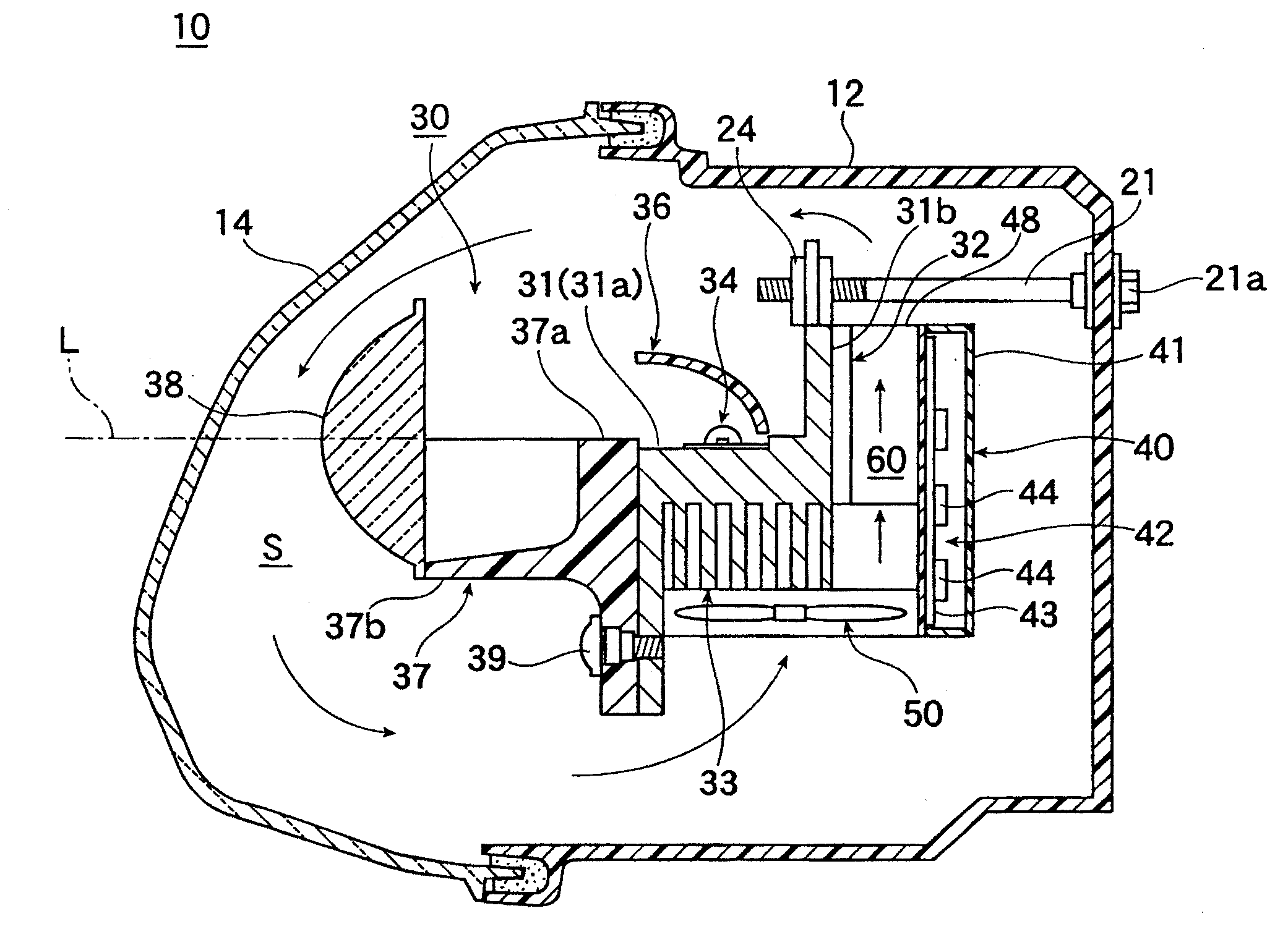
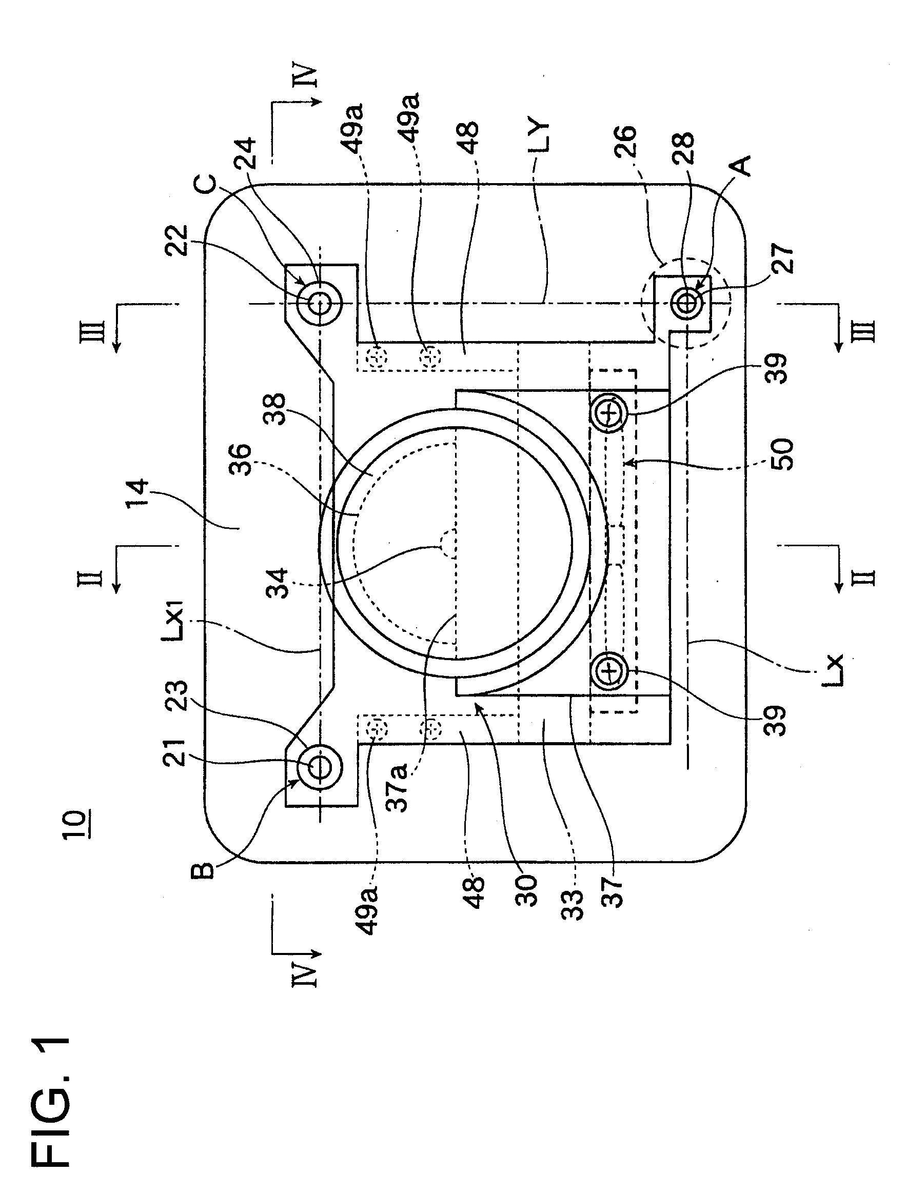
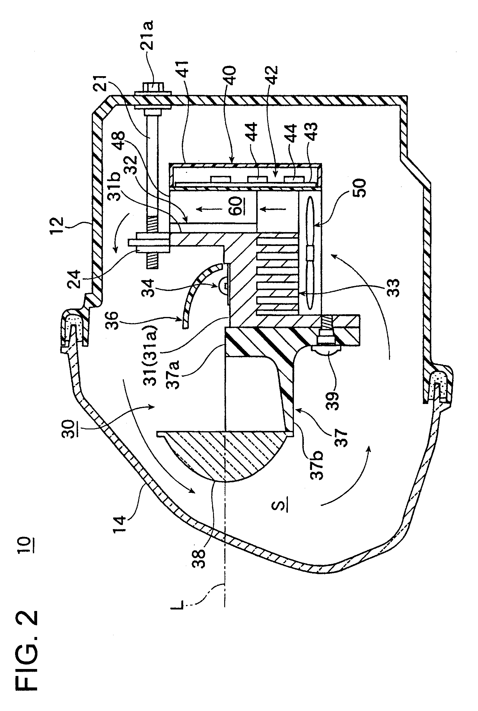
[0041]FIGS. 1 to 4 show a vehicular headlamp in accordance with one or more embodiments of the present invention. FIG. 1 is a frontal view of the headlamp. FIG. 2 is a vertical cross-sectional view of the headlamp (cross-sectional view along a line II-II) shown in FIG. 1. FIG. 3 is a vertical cross-sectional view of the headlamp (cross-sectional view along a line III-III shown) in FIG. 1. FIG. 4 is a horizontal cross-sectional view of the headlamp (cross-sectional view along a line IV-IV) shown in FIG. 1.

[0042]Referring to these drawings, in a vehicular headlamp 10, a lamp chamber S is formed by a lamp body 12 and a generally plain translucent cover (front cover) 14 that is attached to a front opening portion of the lamp body 12. A projector type light source unit 30 having a light-emitting element 34 as a light source is accommodated inside the lamp chamber S.

[0043]The light source unit...


PUM


Abstract

A vehicular headlamp, wherein a light source unit for light distribution formation is accommodated inside a lamp chamber defined by a lamp body and a front cover, includes a metal heat transfer member that serves as a light source unit structural member; a light-emitting element that serves as a light source; a fan for cooling the light-emitting element provided inside the lamp chamber; and a lighting circuit that controls lighting of the light-emitting element. The light-emitting element, the fan, and the lighting circuit are each attached to the metal heat transfer member.

Description

BACKGROUND OF INVENTION[0001]1. Field of the Invention[0002]The present invention relates to a vehicular headlamp, in which a light source unit for light distribution formation is accommodated inside a lamp chamber that is defined by a lamp body and a front cover, and the light source unit is provided with a metal heat transfer member.[0003]2. Related Art[0004]Various vehicular headlamps have been proposed in recent years with configurations that accommodate a light source unit for light distribution formation, which has a light-emitting element such as a light-emitting diode as a light source, within a lamp chamber in order to reduce power consumption. However, the amount of heat generated by the light-emitting element has become a concern over the course of developing a light-emitting element capable of achieving a high light flux that matches the light intensity required for headlamp light distribution. In other words, while a light-emitting element capable of high light flux can...

Claims


Application Information

Patent Timeline
Patent Type & Authority Applications(United States)
IPC IPC(8): B60Q1/04H01J9/24
CPCF21S48/1159F21S48/325F21V29/76F21V29/02F21V29/677F21S48/335F21S45/60F21S41/148F21S45/435F21V29/67
Inventor INOUE, TAKASHINAMBA, TAKANORI
Owner KOITO MFG CO LTD
Why Eureka
Try Eureka