
Electric storage device and its production method

a technology of electric storage and production method, which is applied in the direction of cell components, final product manufacturing, sustainable manufacturing/processing, etc., can solve the problems of vehicle exhaust gas emission, gas leakage, corrosivity of electrolyte solution, etc., and achieve the effect of accelerating the pre-doping speed, reducing the absolute amount of gas produced by the decomposition of electrolyte solution, and safe us

Active Publication Date: 2010-10-07
SUBARU CORP
View PDF5 Cites 46 Cited by
  • Summary
  • Abstract
  • Description
  • Claims
  • Application Information

AI Technical Summary

Benefits of technology

The present invention aims to provide a technique for reducing and suppressing the expansion of an electric storage device caused by the generation of decomposed gas from the electrolyte solution. This is achieved by using a specific range of materials with a weight-average mesopore / macropore specific surface area as an electrode material. The invention also aims to improve the charging / discharging characteristic of the electric storage device. This technique allows for the safe use of materials that would be otherwise limited due to the expansion of the device caused by the gas generated from the electrolyte solution.

Problems solved by technology

Nowadays, an environmental issue, specifically vehicle-exhaust gas emission, is widely talked about.
In other words, although the feature of the negative electrode material is set within the scope of the claims in JP-A Nos. 2008-150270 and 2007-91557, an expected effect cannot always be obtained.
The significant expansion of the electric storage device, which is caused in some cases, might cause a leakage of the electrolyte solution that has corrosivity or a leakage of gas because the electric storage device is opened.

Method used


Image

  • Electric storage device and its production method
  • Electric storage device and its production method
  • Electric storage device and its production method

Examples


embodiment 1

[0097]In the present embodiment, it is described an electric storage device employing the above-mentioned structure in which the negative electrode material having the weight-average mesopore / macropore specific surface area within the specific range is used. The electric storage device can be configured as a lithium ion capacitor, for example. The electric storage device can also be configured as a lithium ion secondary battery.

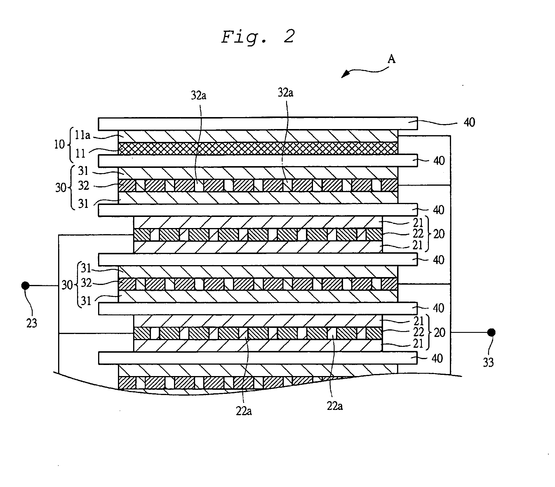
[0098]FIG. 2 schematically illustrates an electrode structure when the electric storage device is configured as a lithium ion capacitor. As illustrated in FIG. 2, for example, the electric storage device is configured as a stacked-type lithium ion capacitor A. The lithium ion capacitor A includes a lithium electrode 10, positive electrodes 20, and negative electrodes 30. A plurality of positive electrodes 20 and negative electrodes 30 are alternately stacked in a state that a separator 40 is interposed between each of the positive electrodes 20 and each of th...

embodiment 2

[0126]In the present embodiment, the electric storage device is configured to be a lithium ion secondary battery B. As illustrated in FIG. 3, the lithium ion secondary battery B is configured to be a stacked type. The lithium ion secondary battery B includes lithium electrodes 100, positive electrodes 200, and negative electrodes 300. A plurality of positive electrodes 200 and negative electrodes 300 are alternately stacked in a state that a separator 400 is interposed between each of the positive electrodes 200 and each of the negative electrodes 300. The negative electrode 300 is provided at the outermost part of the stacked electrode group. The lithium electrode 100 serving as an ion source is provided so as to face the negative electrode 300 arranged at the outermost part of the stacked structure through the separator 400. The stacked unit described above is soaked in electrolyte solution.

[0127]As illustrated in FIG. 3, the lithium electrode 100 has, for example, a metal lithium...

example 1

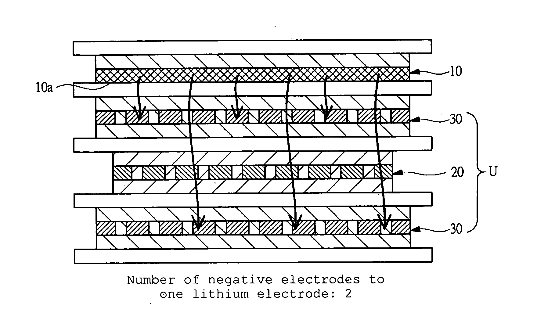
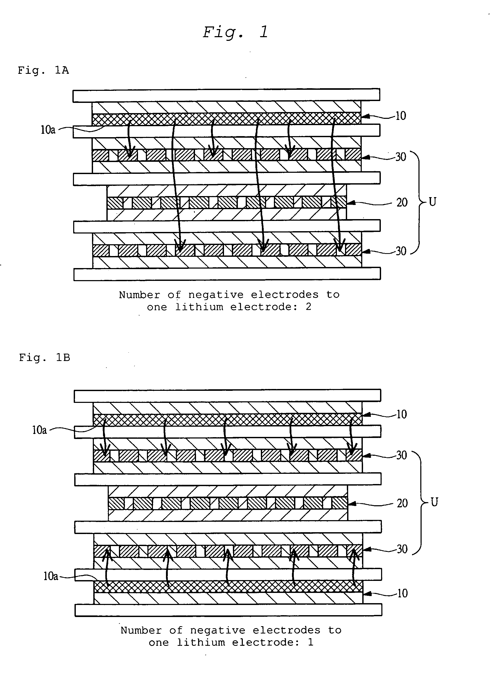
[0149]In the Example 1, plural lithium ion capacitors were produced, and the experiment was conducted. Each of the lithium ion capacitors includes a positive electrode whose average air permeability is greatly different from one another. The negative electrode material used for the negative electrode of each of the lithium ion capacitors allows lithium ions to be doped and de-doped. Further, the negative electrode material used for the negative electrode of each of the lithium ion capacitors has a weight-average mesopore / macropore specific surface area within the specific range. In the respective lithium ion capacitors, the combined air permeability and the number of the negative electrodes to one lithium electrode facing the electrode unit, i.e., the numerical index X, is different from one another.

[0150]In the lithium ion capacitor, after a cell was completed, a lithium electrode terminal and a negative electrode terminal were short-circuited so as to dope lithium ions into the ne...


PUM

PropertyMeasurementUnit
specific surface areaaaaaaaaaaa

Abstract

When an electrode material having a weight-average mesopore / macropore specific surface area within a specific range is used, there arises an expansion of a cell caused by the generation of decomposed gas from a component of electrolyte solution during the pre-doping process of lithium ions. A potential drop upon the pre-doping process is adjusted so as to reduce or suppress the expansion of the cell. Specifically, since the pre-doping speed is increased, the negative electrode can speedily reach the potential by which an SEI component made of lithium alkyl carbonate can be produced on the surface of the negative electrode. Consequently, the absolute amount of the gas produced by the decomposition of the electrolyte solution can be reduced, whereby the expansion of the electric storage device can be reduced.

Description

CROSS-REFERENCE TO RELATED APPLICATIONS[0001]The present application claims priority from Japanese Patent Application No. 2009-079114 filed on Mar. 27, 2009, and is hereby incorporated by reference in its entirety.BACKGROUND OF THE INVENTION[0002]1. Field of the Invention[0003]The present invention relates to an electric storage device, and its production method, and more particularly to a technique well adaptable to reduce and suppress the expansion of an electric storage device, which is caused by the generation of decomposed gas from a component of electrolyte solution, in case where a material having a weight-average mesopore / macropore specific surface area within a specific range is used for an electrode material.[0004]2. Description of the Related Art[0005]The technique described below has been studied for completing the present invention. The summary is as follows.[0006]Nowadays, an environmental issue, specifically vehicle-exhaust gas emission, is widely talked about. In thi...

Claims


Application Information

Patent Timeline
Patent Type & Authority Applications(United States)
IPC IPC(8): H01M6/10H01M6/00H01G9/00H01G11/06H01G11/14H01G11/22H01G11/24H01G11/30H01G11/42H01G11/52H01G11/54H01G11/62H01G11/66H01G11/70H01G11/84H01G11/86H01M4/02H01M4/133H01M4/58H01M4/587H01M4/70H01M10/0525H01M10/0566H01M10/0585H01M10/0587H01M10/36
CPCH01G11/06Y10T29/49108H01G11/24H01G11/62H01G11/70H01M4/133H01M4/742H01M4/745H01M10/0525H01M12/005H01M2004/021Y02E60/122Y02E60/13Y02T10/7011Y02T10/7022H01G9/016H01G9/058H01G9/038H01G9/155H01G11/12Y02T10/70Y02E60/10Y02P70/50H01G11/50H01G11/86H01G11/32H01G11/46H01G11/22H01G11/74
Inventor FUJII, TSUTOMUHATOZAKI, OSAMU
Owner SUBARU CORP
Learn More