Drive assist device and method for motor driven truck

a technology for mining trucks and assist devices, which is applied in the direction of electric devices, propulsion using engine-driven generators, process and machine control, etc., can solve the problems of increased fuel consumption of retarded trucks, difficulty for drivers to estimate appropriate coasting distances, and increased truck speed, so as to reduce fuel consumption and reduce the operational cost of mining trucks , the effect of reducing fuel consumption

Inactive Publication Date: 2010-10-07
NIHON KENKI CO LTD
View PDF4 Cites 27 Cited by
  • Summary
  • Abstract
  • Description
  • Claims
  • Application Information

AI Technical Summary

Benefits of technology

[0007]Reduction of fuel consumption significantly contributes to the reduction of the operational costs of mining trucks. One of the possible methods for reducing fuel consumption is to retard the trucks, which can make engine's fuel consumption low. However, trucks with diesel-electric transmissions tend to decrease the rate of consumed fuel against output of a primary power source, in short, the fuel consumption rate with an increase in truck speed, and therefore, retardation of the truck may consume more fuel.

Problems solved by technology

However, trucks with diesel-electric transmissions tend to decrease the rate of consumed fuel against output of a primary power source, in short, the fuel consumption rate with an increase in truck speed, and therefore, retardation of the truck may consume more fuel.
During coasting the vehicle propels with inertial energy; however, it is difficult for a driver to estimate an appropriate coasting distance because the mining trucks carry loads that are heavier than truck's body weights and are different in amount every time the loads are put on the trucks.
If the driver overestimates the coasting distance by mistake, the truck reduces speed more than necessary and consequently requires extra acceleration energy.
This reduces benefits of the fuel-efficient driving method.

Method used


Image

  • Drive assist device and method for motor driven truck
  • Drive assist device and method for motor driven truck
  • Drive assist device and method for motor driven truck

Examples


first embodiment

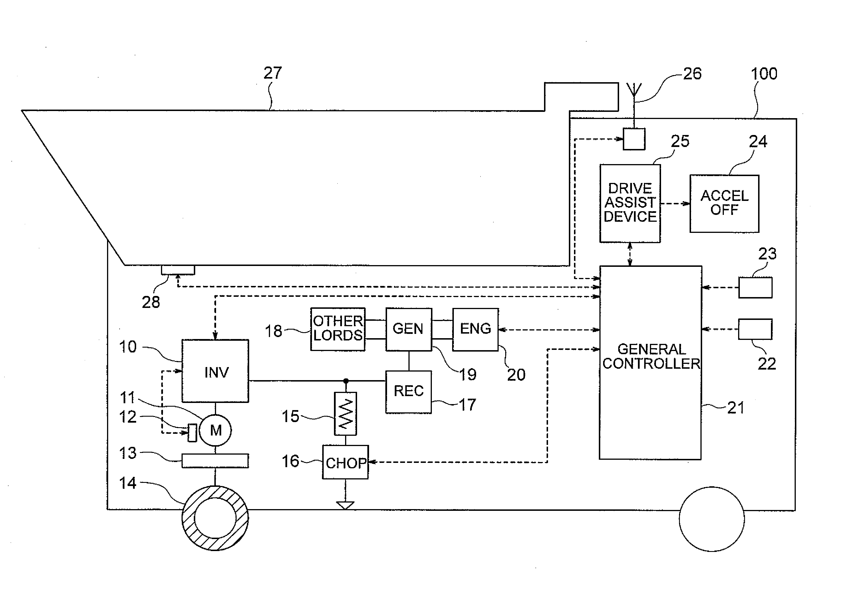
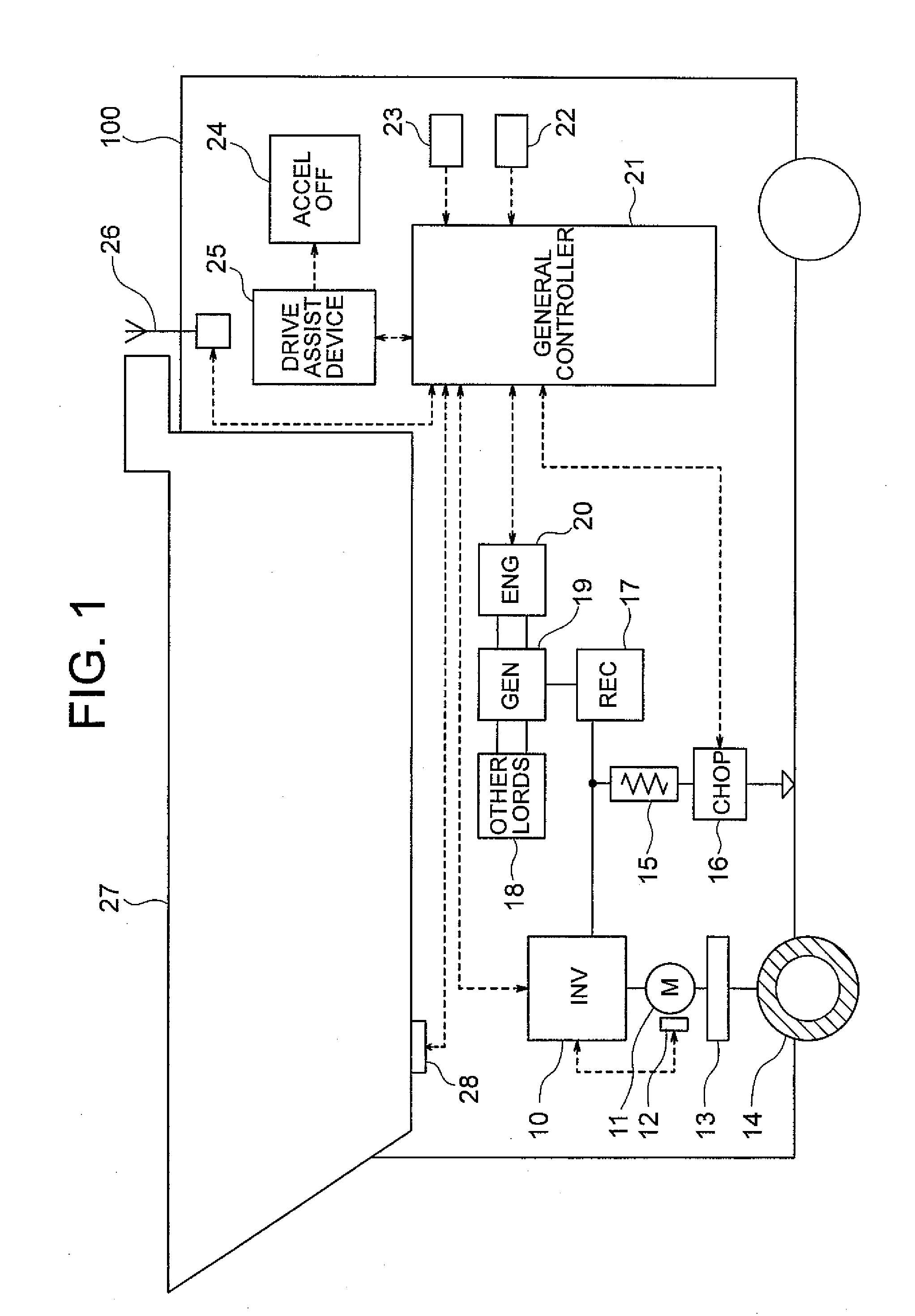
[0027]FIG. 1 is a schematic diagram of the diesel-electric driven mining truck system with a drive assist device therein according to the first embodiment of the present invention.

[0028]In a diesel-electric driven truck 100 of FIG. 1, an engine 20 drives an AC generator 19 to output AC power that is rectified by a rectifier 17 to obtain DC power. The obtained DC power is converted by an inverter 10 into three-phase AC power with variable voltage and variable frequency to drive an induction motor 11 while adjusting the speed of the motor 11. The induction motor 11 is connected with a drive tire 14 via a decelerator 13 and propels the truck 100.

[0029]Brakes applied on the truck 100 causes the induction motor 11 to generate regenerative electric power that is dissipated as heat by a grid resistor 15 through control of a chopper circuit 16.

[0030]The AC generator 19 is connected with some other loads 18 including accessory equipment such as an oil pump.

[0031]In order to control the compo...

second embodiment

[0088]FIG. 6 is a schematic diagram of the diesel-electric driven mining truck system installed with an external drive assist device according to the second embodiment of the present invention. The drive assist device 25 is connected to a wireless communication device 30 and can wirelessly communicate with the truck. The truck 100 is provided with a wireless communication device 29 that is connected to the general controller 21 so that the general controller 21 of the truck 100 and the drive assist device 25 can mutually communicate through the wireless communication devices 29, 30. The guidance display 24 is connected to the general controller 21. The drive assist device 25 receives information for calculating coasting deceleration distance from the general controller 21 through wireless communication, and feeds back an instruction to display the initiation of coasting through the wireless communication to the general controller 21 that sends the instruction to the guidance display...

third embodiment

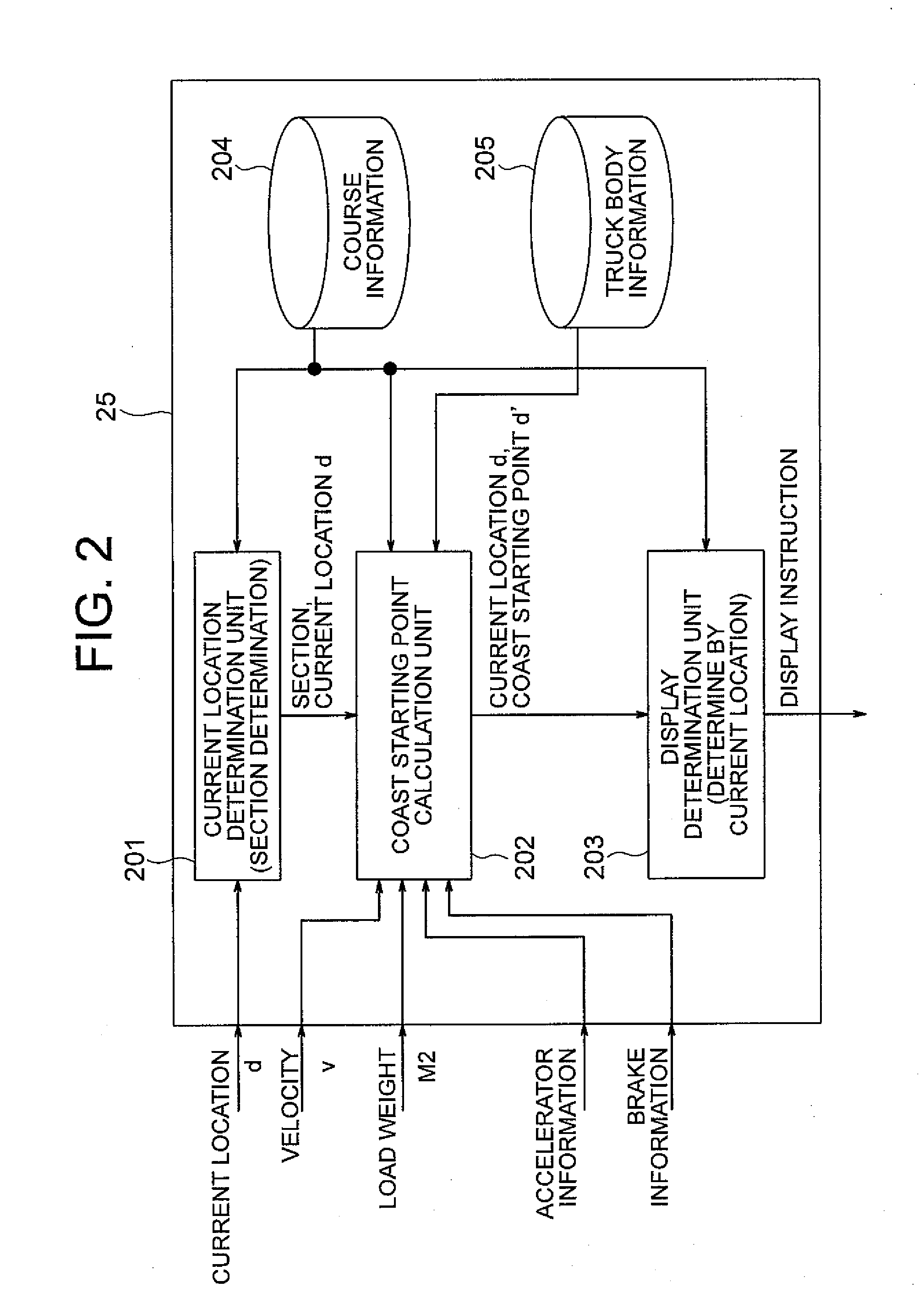
[0090]FIG. 7 is a function block diagram schematically showing the drive assist device 25 including a running resistance calculation unit according to the third embodiment of the present invention.

[0091]Although, in the first embodiment, the running resistance is calculated from surface resistance and inclination stored in the course information, the drive assist device 25 in the third embodiment includes a running resistance calculation unit 206 that calculates running resistance while the truck is travelling. The running resistance is used to calculate coasting deceleration distance Δd. The other components are the same as those in FIG. 2.

[0092]Next, methods for calculating a running resistance coefficient and a coast starting point will be described.

[0093]The expressions 1 to 4 are integrated to obtain expression 9 for the running resistance coefficient μ.

[Equation8]μ=1(M1+M2)g[2GRTE-(M1+M2+2G2JR2)vt](8)

[0094]Thus, with output torque TE of the induction motor 11 input from the ge...


PUM


Abstract

A drive assist device for a diesel-electric driven truck is provided to guide and assist a driver in starting to coast so that appropriate coasting deceleration suitable for load weight is realized. The drive assist device includes a course information database that stores information about a course, a truck body information database that stores information about the truck body, a current location determination unit that calculates current location information, a coast initiation timing calculation unit that calculates timing of coasting based on a current location and velocity of the truck and a target velocity at a predetermined point ahead of the truck, those of which being obtained from the databases and input information, the timing of coasting being used to achieve the target velocity at the predetermined point and a guidance unit that informs a truck driver of the timing of coasting according to an output of the calculation unit.

Description

BACKGROUND OF THE INVENTION[0001]1. Field of the Invention[0002]The present invention relates to a drive assist device for mining trucks driven by an electric motor, and particularly to a drive assist device and a drive assist method for instructing a driver of the time to start to coast.[0003]2. Description of the Related Art[0004]There are two kinds of well-known drive systems for haul trucks used in mines: a mechanical transmission in which torque is mechanically transferred from a primary power source to tires; and a diesel-electric transmission, as disclosed in JP-A No. 2001-1077621, in which a primary power source drives an electrical generator to generate electric power that drives a drive motor.[0005]The truck with the diesel-electric transmission does not use a mechanical brake to damp itself, but employs a braking system in which a motor generates a braking torque and inner resistors consume regenerative energy generated by the motor. The present invention especially relat...

Claims


Application Information

Patent Timeline
Patent Type & Authority Applications(United States)
IPC IPC(8): G06F19/00B60K6/46B60L15/20B60L15/40B60L50/15B60W10/06B60W10/08B60W20/00
CPCB60K6/46Y02T10/70B60L11/02B60L2210/20B60L2240/26B60L2240/62B60L2260/24B60W10/06B60W10/08B60W20/00B60W2520/10B60W2530/10B60W2540/10B60W2540/12B60W2550/402Y02T10/6217Y02T10/6286Y02T10/7077Y02T10/725Y02T10/7258Y02T10/7291Y02T90/16Y02T90/162B60L3/12B60L50/10B60W2556/50Y02T10/62Y02T10/72Y02T10/60Y02T10/7072B60W2050/146B60W2300/12B60W20/10
Inventor SASAKI, MASATAKAKIKUCHI, AKIRAFUTAMI, MOTOONAKAJIMA, KICHIOYASUDA, TOMOHIKO
Owner NIHON KENKI CO LTD
Why Eureka
Try Eureka