
Cooling Device, Cooling Arrangement and Lithographic Apparatus Comprising a Cooling Arrangement

a cooling device and cooling arrangement technology, applied in the field of cooling devices, can solve the problems of vibration of the cooling chuck by the thermal transfer liquid, the application of the apparatus, etc., and achieve the effects of good heat transfer, low thermal expansion coefficient, and easy assembly

Active Publication Date: 2010-10-14
ASML NETHERLANDS BV
View PDF13 Cites 11 Cited by
  • Summary
  • Abstract
  • Description
  • Claims
  • Application Information

AI Technical Summary

Benefits of technology

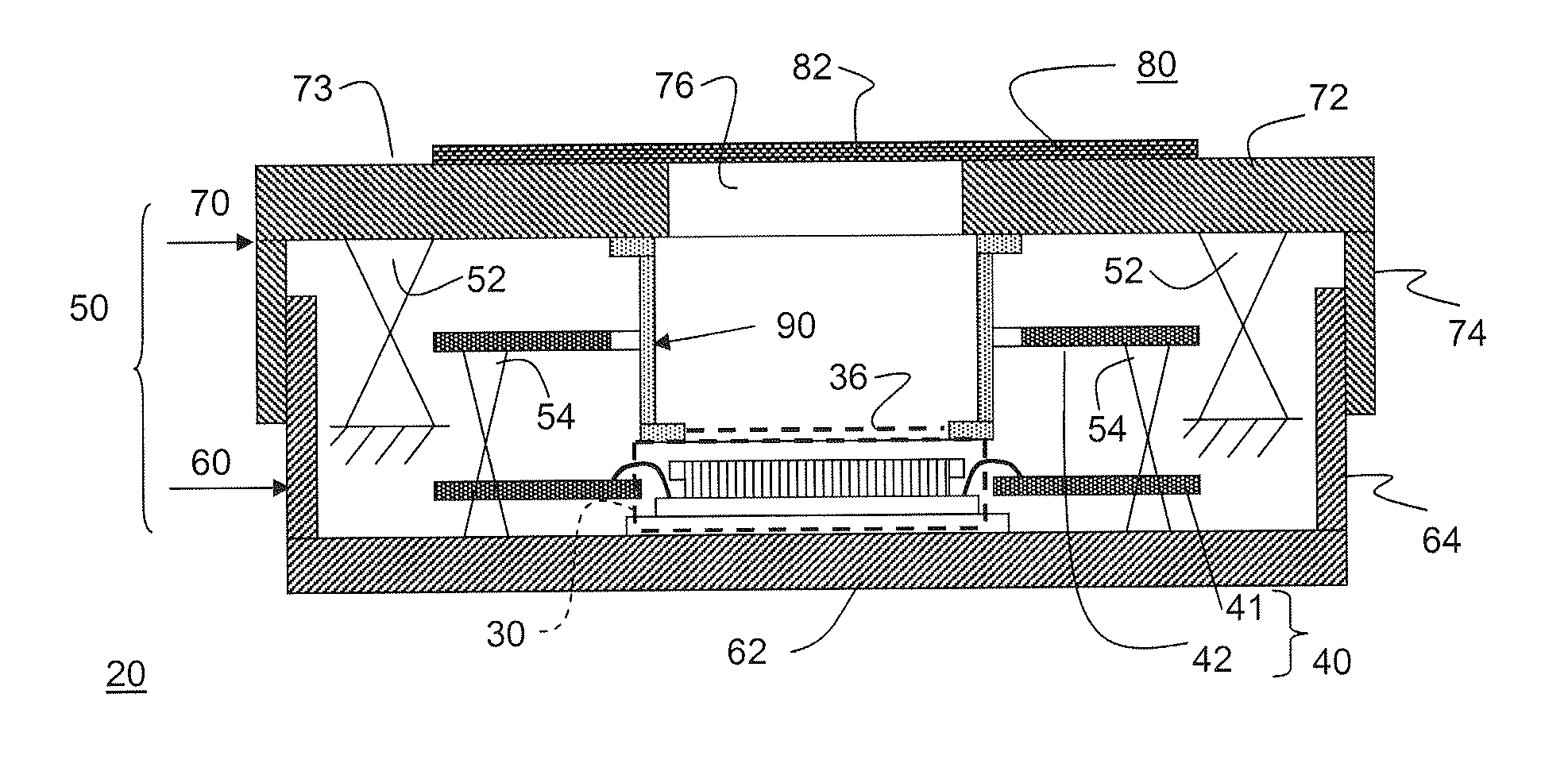
[0018]In an embodiment, the gap mechanically decouples the object from the heat sink so that transmission of possible vibrations from the heat sink to the detector module, e.g. caused by the flow of a cooling liquid, is mitigated. Nevertheless, the gap between the detector module and the heat sink is at least substantially separated from the environment of the cooling arrangement, so that the space comprising the gap can be filled with a gas, even if the cooling arrangement is arranged in a vacuum environment. The gap filled with the gas allows for an efficient transport of heat from the detector module to the heat sink. The object to be cooled may be an optical component, but may alternatively be a detector as is described in more detail below. It is noted that United States Patent Application Publication No. 2005 / 0008983, which is incorporated herein by reference in its entirety, describes an apparatus for supporting a workpiece in a process chamber. The apparatus includes a first “hot” chuck having a surface for supporting the workpiece, the hot chuck including electrical heating elements for heating the hot chuck, and a second “cold” chuck having a fluid path formed therein for circulating a thermal transfer fluid. The cold chuck can be selectively movable towards and away from the hot chuck to vary a rate of heat transfer between the hot chuck and the cold chuck. The process chamber is used to carry out various processing steps. In a preferred embodiment of the known apparatus, a gas is continuously injected into the gap between the chucks. This allows heat to be transferred from the hot chuck to the cold chuck by “free convection” and (to some extent) conduction through the gas.
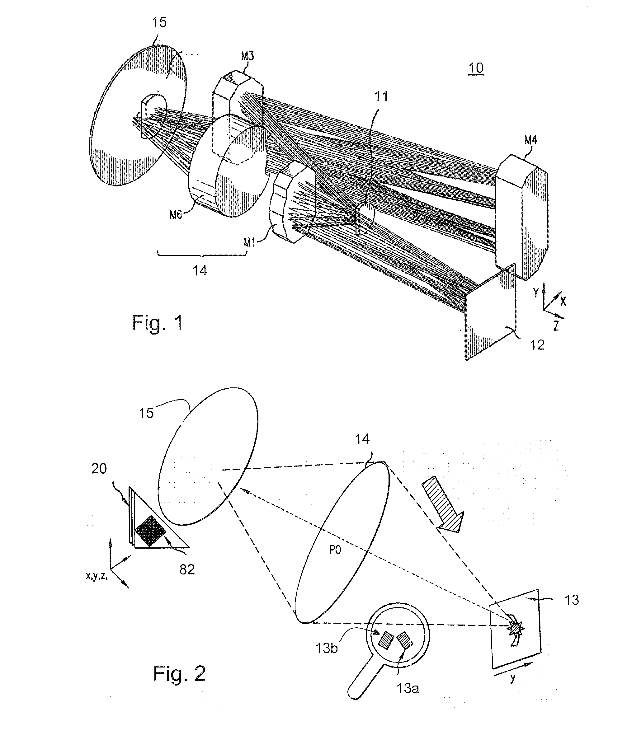
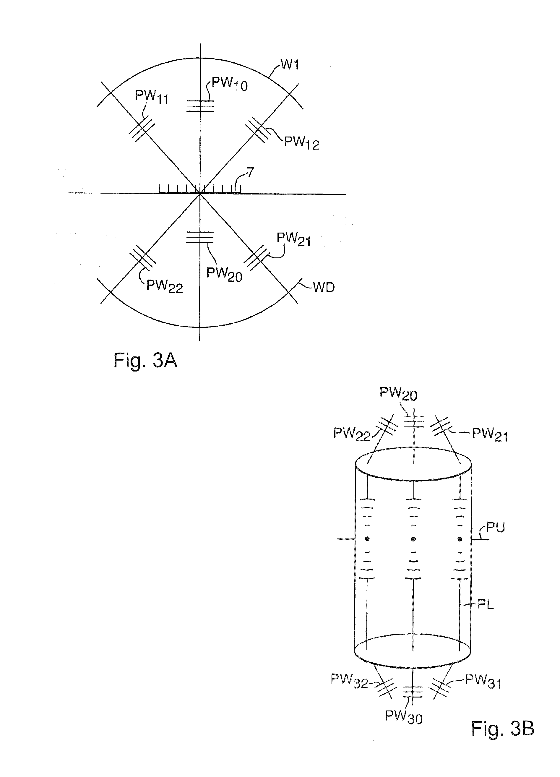
[0041]According to a further embodiment, a method of measuring a wavefront includes directing electromagnetic radiation from a source to an object plane so as to illuminate the object plane, projecting an image of a first grating positioned in the object plane onto a focal plane at a detector module, and cooling the detector module using a heat sink and a resilient wall, such as described in the embodiments discussed above. Wavefront aberrations caused, for example, by an optical system in the optical path of the electromagnetic radiation can then be inspected or measured at the focal plane. The cooling of the detector module prevents various negative effects on the operation of the detector module caused by heat, for example, from the electromagnetic radiation and / or by the circuitry found within the detector module.

Problems solved by technology

In an environment such as the EUV lithographic apparatus that requires a vacuum environment, this apparatus is not applicable.
However the chuck cooled by the thermal transfer liquid is subject to vibrations due to the flow of the liquid.

Method used


Image

  • Cooling Device, Cooling Arrangement and Lithographic Apparatus Comprising a Cooling Arrangement
  • Cooling Device, Cooling Arrangement and Lithographic Apparatus Comprising a Cooling Arrangement
  • Cooling Device, Cooling Arrangement and Lithographic Apparatus Comprising a Cooling Arrangement

Examples


Embodiment Construction

[0063]This specification discloses one or more embodiments that incorporate the features of this invention. The disclosed embodiment(s) merely exemplify the invention. The scope of the invention is not limited to the disclosed embodiment(s). The invention is defined by the claims appended hereto.

[0064]The embodiment(s) described, and references in the specification to “one embodiment”, “an embodiment”, “an example embodiment”, etc., indicate that the embodiment(s) described can include a particular feature, structure, or characteristic, but every embodiment cannot necessarily include the particular feature, structure, or characteristic. Moreover, such phrases are not necessarily referring to the same embodiment. Further, when a particular feature, structure, or characteristic is described in connection with an embodiment, it is understood that it is within the knowledge of one skilled in the art to effect such feature, structure, or characteristic in connection with other embodiment...


PUM

PropertyMeasurementUnit
thermal conductivityaaaaaaaaaa
areaaaaaaaaaaa
widthaaaaaaaaaa

Abstract

A cooling arrangement is described and includes a heat sink having a first thermal contact surface, an object having a second thermal contact surface and a resilient wall. The first thermal contact surface and the second thermal contact surface face each other and define a gap. The resilient wall is part of an enclosure that surrounds a space at least comprising the gap, and the cooling arrangement includes a facility to maintain a pressure difference between the space and an environment of the cooling arrangement. Additionally, a lithographic apparatus comprising such a cooling arrangement is described.

Description

CROSS REFERENCE TO RELATED APPLICATIONS[0001]This patent application claims the benefit of U.S. Provisional Patent Application No. 61 / 168,710 filed on Apr. 13, 2009, entitled “Cooling Device, Cooling Arrangement And Lithographic Apparatus Comprising Cooling Arrangement”, which is incorporated by reference herein in its entirety.BACKGROUND OF THE INVENTION[0002]1. Field of the Invention[0003]The present invention relates to a cooling device, and further relates to a cooling arrangement. The present invention still further relates to a lithographic apparatus comprising a cooling arrangement.[0004]2. Background Art[0005]Lithography is a process used to create features on the surface of substrates. Such substrates can include those used in the manufacture of flat panel displays, circuit boards, various integrated circuits (ICs), and the like. A frequently used substrate for such applications is a semiconductor wafer. One skilled in the relevant art will recognize that the description he...

Claims


Application Information

Patent Timeline
Patent Type & Authority Applications(United States)
IPC IPC(8): G03B27/52H01J7/24F28F7/00H01L23/467B23P11/00
CPCG03F7/70858G03B27/52G03F7/7085Y10T29/49826G03F7/70825H01L21/67109
Inventor KNARREN, BASTIAAN ANDREAS WILHELMUS HUBERTUSTURK, RAYMONDKOOIKER, ALLARD EELCOBOONEN, NICO ANTONIUS JOHANNES HUBERTUS
Owner ASML NETHERLANDS BV
Learn More